Index Typical installations 2 Components of system 3 Seven Step Installation Step #1: Choose your system 3 Step #2: Plan number of inlets 4 Step #3: Plan placement of inlets 4 Step #4: Plan tubing installation 5 Step #5: Install inlet valves Existing home 5 New construction 8 Step #6: Install tubing 9 Step #7: Install power unit Safety warnings 10 12
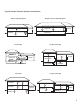
Typical Central Vacuum System Installations Single story on slab/crawlspace Ranch-style bungalow MAIN FLOOR 1 BASEMENT 3 GARAGE MAIN FLOOR 4-level split Large 4-level split UPPER LEVEL MAIN FLOOR 1 UPPER LEVEL 1 LOWER LEVEL GARAGE 3 3 2 CRAWLSPACE 3 2 1 MAIN FLOOR 3 3 GARAGE LOWER GARAGE 5 LEVEL 2 2 4 CRAWLSPACE CRAWLSPACE BASEMENT Large 3-level split Two-story 1 UPPER LEVEL BASEMENT 1 UPPER LEVEL 1 MAIN FLOOR MAIN FLOOR 2 4 GARAGE 3 LOWER LEVEL 2 BASEMENT 3 4
Seven Step Installation Congratulations on the purchase of your new central vacuum system. It will make cleaning your home easier and improve indoor air quality. The system typically can be installed in virtually any home with no costly alterations and very little mess. This guide will show how to install your central vacuum system in your home in just seven steps. Before you begin installation, read this guide. Also review local building codes so your installation complies with them.
Installation Step 2: Decide how many inlets you will need. To make sure your central vacuum system reaches every room throughout the house, you must first determine the number of inlets you will need and where to place them. One inlet valve can serve 700-800 square feet (63-72 sq m). Use only interior walls if possible, so you won’t have to deal with insulation typically found in exterior walls. Choosing the right spot for the inlet valve.
Deciding where to mount the power unit. To be sure that dust and dirt are effectively removed from living areas in your home, mount the power unit in your attached garage. If you do not have an attached garage, the basement, utility room, storage room or mud room is the best alternative location. Find a spot that is close to an electrical source, yet with plenty of room for air to circulate on either side of the unit. You’ll need a dedicated 15- or 20-amp circuit. Check the owner’s manual.
Installing an inlet valve. Take a wall mounting bracket, cut or snap off the new construction flange and dispose of it. In new construction, nail the tab to the stud. (See New Construction inlet valve installation.) Use a level to make sure the mounting bracket is level. Then trace the outline of the mounting bracket onto the wall. Take a utility knife and score the lines. Then use the utility knife or a drywall saw to cut a hole though the drywall. Hint: A drywall saw makes the job easier.
Enlarge the hole in the exterior wall to accommodate the inlet valve assembly (valve and mounting bracket). (As described above in “Installing an inlet valve.”) Inside the closet, drill a pilot hole through the floor beneath the opening in the wall or at a convenient spot nearby to check for obstructions. If there are no obstructions, cut a 2-1/4" (5.7cm) hole through the floor. Run low-voltage wire through the hole in floor, and through the wall to exterior of closet. Fig. 02 Floor valve installation.
Remember: Apply glue only to the outside of the tubing. Hint: When upstairs, remember to aim the elbow downward. Other ways to reach the upstairs in your home are through the interiors of closets or pantries, beneath a staircase, or with floor inlets. If the inlet valve will be serviced from the attic, shorter pieces of tubing joined by couplings may be required because of overhead space restrictions. Again, measure and test fit.
Drop bottom of tubing through 2-1/4" (5.7cm) hole and nail stud-mounting bracket assembly to stud. Make sure the center of the inlet hole is at the correct height above floor level and the tubing extends below the sub-flooring. To prevent a nail or screw from penetrating the vacuum tubing, install nail guards on the sole or top plates adjacent to the tubing. See “Installation Step Six: Install the tubing” and complete tubing installation as much as possible.
Connect tubing from additional inlet valves to the main trunk line using 90 degree sweep tee elbow fittings. (Fig. 07) and use clamps to hold the sections in place. Be sure to install the sweep tee fittings so the sweep is toward the power unit (Fig. 08). Always run branch lines from the sides or top of the main trunk line, never out of the bottom because this will create a trap for dirt to fall into. Fig. 07 Hint: Create clamps from extra tubing to hold lowvoltage wire in place.
To attach the low-voltage wires, strip the wire and crimp the strands into the two “slip-on” terminals provided. Attach the terminals and plug the power unit into the dedicated electrical outlet. The sentry light should come on. Flip the switch and the power unit should come to life. Attach the remaining section of tubing to the power unit with connector/s and clamp/s provided. Caution: Do not glue the connection because you may need to disconnect the system at a future date.
WARNING: ELECTRIC SHOCK COULD OCCUR IF USED ON WET SURFACES. GROUNDING INSTRUCTIONS This appliance must be grounded. If it should malfunction or break down, grounding provides a path of least resistance for electric current to reduce the risk of electric shock. This appliance is equipped with a cord that has an equipment-grounding conductor and grounding plug. The plug must be plugged into an appropriate outlet that is properly installed and grounded in accordance with all local codes and ordinances.
IMPORTANT SAFETY INSTRUCTIONS When using electrical appliances, basic safety precautions should always be followed, including the following: DANGER: Always unplug power unit from the electrical outlet before servicing and cleaning. WARNING: To reduce the risk of burns, fire, electric shock or injury to persons: 1. Keep cord away from heated surfaces. 2. Do not allow to be used as a toy. Close supervision is necessary when this vacuum is used by or near children. 3.