F4VA1 Shirt finisher Usage and Maintenance F4VA1-ed3605
F4VA1-ed3605
F4VA1 Index 3 Index 1. Introduction 1.1. Content and purpose of this manual 1.2. Safety precautions 1.3. Residual risks 1.4. Manufacturer’s liability 4 2. Description of the machine 2.1. How to identify the machine 2.2. Technical specifications 5 3. Installation 3.1. Upon receiving the goods 3.2. Packing list 3.3. Electrical connections 3.4. Compressed air connection 3.5. Steam connection 6 4. Use 4.1. Safety precautions 4.2. Before starting 4.3. Operation 4.4. In case of emergency 4.5.
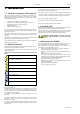
Introduction 4 1. Introduction 1.1. Content and purpose of this manual This manual contains instructions concerning the installation and maintenance of pressing equipment in conformity to the present European Community Directive. Therefore you will find information on the following subjects: • • • • • Information on machine technical features; Instructions on installation and operating of the machine. Instructions on maintenance and servicing.
F4VA1 5 Description of the machine Description of the data in the identification plate 2. Description of the machine The unit described in this manual is a form finisher for pressing wet shirts. This shirt finisher is designed for: • Garment manufacturing industries; • Large and small Industrial dry cleaners; • Garment finishing industries. The shirt finisher must be utilized by only qualified personnel, who have been specifically trained on this type of machinery.
Installation 6 3. Installation 3.1. Upon receiving the goods The machine is delivered mounted on crate and protected by a plastic film and, in some cases, by a cardboard box. 1. Position the crated machine near to the final location of installation. The crated machine must be moved using suitable devices, such as a forklift (Figure 3.1) 2. Unpack the machine and separate cardboard from plastic. Dispose of carton and plastic according to local regulations. 3.
F4VA1 Installation Figure 3.1 - How to move the crated machine Figure 3.2 - Assembling the mirror Figure 3.3 - Electrical connection ! min 16A @ 400V 50Hz min 25A @ 220V 60Hz Figure 3.5 - Steam connections Figure 3.
Use 8 4. Use The form finisher here described is made for pressing wet cleaned shirts. This shirt finisher is designed for: • Garment manufacturing industries; • Large and small Industrial dry cleaners; • Garment finishing industries. The shirt finisher must be utilized by qualified personnel, who have been specifically trained on this type of machinery. 4.1.
Use F4VA1 Figure 4.1 - How to clamp the cuff Figure 4.2 - Control panel (A) (B) (C) (D) (E) Figure 4.
The higher the value displayed by gauge (15), the lower the tension on the sleeves. To adjust the tnesion, pull knob (20) and turn to change the value displayed. Push the knob to lock the value**. Sleeve arms counter-pressure: This pressure determines how fast the sleeve arms return to their rest position after releasing the shirt cuffs. Check periodically that the value displayed by gauge (16) is correct*. Otherwise, pull knob (19) and rotate to adjust the pressure.
F4VA1 Use of the control board 5. Use of the control board Figure 5.3 - Displays during advanced parameters programming The microprocessor programmer manages the pressing cycle in all of its functions. The user can pre-set 9 pressing programs. The control panel is subdivided into 4 sections: • PROGRAMMING: allows storage of 9 different work programs with programmable times and modes. • EXCLUSION: allows partial or total exclusion of various pressing functions.
Use of the control board F4VA1 5.5. MANUAL CONTROLS section AIR Press once to start blowing. Press it again to stop blowing. In order to have manual MIX press STEAM during the blowing operation. REPEAT CYCLE Repeats the cycle without further tensioning; this button is enabled only at end of the pressing cycle and only if the MANUAL END mode is selected. END CYCLE Ends the cycle immediately, interrupts all ongoing commands, opens all clamps.
Use of the control board F4VA1 13 Table 5.1 - Setting mix and pause times What is your need? What you should do How the displays will look I do not need mix or pause Set both times at zero times Mix and pause lights are off. The displays show no numbers. I want both mix and air times Set the two times according to the procedure described in chapter 5.1.1. Note that each of the two times cannot exceed 9 seconds. Mix and pause lights are on. The digit on the left is mix time.
Mainenance 14 F4VA1 6. Maintenance 6.1.2. Every six months 6.1. Maintenance allowed to the user 6.2. Maintenance to be carried out by the technician every six months WARNING: Before performing any maintenance on the machine, disconnect from electric power. Call the authorised technician to perform the maintenance operations described in the following chapter. WARNING: The maintenance operations described in this chapter must only be carried out by qualified personnel. 6.1.1.
F4VA1 7. Troubleshooting Refer to Table 7.4 for solutions to the most common malfunction situations. If the proposed solutions do not work, enter self-diagnosis (paragraph 7.1) to determine if there are failed components. WARNING - DO NOT SERVICE THE MACHINE YOURSELF Call the service center in any of the following cases: • • • 15 Troubleshooting the machine has a problem that is not listed in table 7.
Troubleshooting F4VA1 Table 7.
F4VA1 Machine stop 8. Machine stop 17 Figure 8.1. - How to screw the machine to the crate 8.1. Prolonged stop In case of prolonged stop of the machine: 1. Close steam and air connections 2. Disconnect from electrical power 3. Discharge the pressure in the air circuit 4. Discharge residual condensate 5. Clean the cabinet and the grids from dust and lint 6. Protect the form so that the covers do not get dirty Figure 8.2. - How to pack the machine for transportation 8.2.
F4VA1 F4VA1-ed3605
F4VA1 Diagrams 19 9. Technical diagrams The diagrams in this chapter are for the exclusive use of the authorized assistance center. Do not perform maintenance on the machine if not authorized in writing by the Manufacturing Company.
Diagrams F4VA1 Cuff clamp left Steam Cuff clamp right &YUSB Metal deflector Blower motor control switch RT = Thermal relay Collar clamp Suction Suction motor control switch Front hem clamps Rear clamp Front clamp side movement Sleeve arms position Front hem clamps relay Front clamp open/close Sleeve arms release Right cuff clamp button Left cuff clamp button Front clamp micro switch Start pedal Photocell * Non-standard features: available only on some models or only upon request CONTROL BOARD CONNE
F4VA1 Diagrams 21 Sleeve arms damper Microswitch arms up Microswitch arms down Side clamps exclusion Side expanders close Side expanders close aux relay Side expanders open. SW2 = microswitch; M9 = Antistretching exclusion button Side clamps Carriage up Carriage down M8 = Carriage down button Power supply 24V + Power supply 0V Shoulders close. M3 = button Shoulders open.
Diagrams F4VA1 Sleeve arms motion Damper Raise Release Collar clamp Front clamp open/close Front clamp safety Front clamp side movement Suction Shoulders movement Carriage F4VA1-ed3605
F4VA1 Diagrams 23 Rear clamp Side clamps Left cuff clamp Right cuff clamp Expanders movement E1 Elettrov. Fermacollo Collar clamp valve P4 Pistone traslazione pala frontale E2 Elettrov. Aspirazione Suction valve P5 Pistone apri/chiudi pala frontale Front clamp open/close cylinder E3 Elettrov. Pala posteriore Rear clamp valve P6.7 Pistone posizionamento braccio SX Left arm positioning cylinder E4 Elettrov. Traslazione pala anteriore Front clamp side movement valve P6.
Spare parts F4VA1 10. Spare parts diagrams Please refer to the following diagrams when ordering spare parts. To avoid mistakes, always provide code and description of the required spare part. Always use original spare parts. 2 1 pos 0220581 0220574 Code 1 1 PEDALE MICRO PEDALE PEDALE MOBILE PEDAL MICROINTERRUPTEUR MIKROSCHALTER PEDAL MICRO PEDAL MICROINTERR. PEDAL Q.
F4VA1 14 Spare parts ZC02 1 KIT GUARNIZIONI KIT JOINTS DICHTUNGEN 25 GASKET KIT KIT EMPAQUET. 13 ZC01 2 KIT GUARNIZIONI KIT JOINTS DICHTUNGEN GASKET KIT KIT EMPAQUET. 12 T603040 1 PRONTO TOP PRONTO TOP PRONTO TOP PAD+COVER MULLIDO+TELA COP.
Spare parts F4VA1 7 Z500 1 INTERRUTT. EMERG. INTERRUPT. EMERG. STOP-SCHALTER EMERG. SWITCH INTERRUPT. STOP 6 0221412 1 SCHEDA CARTE ELECTRONIQUE PLATINE CARD TARJETA 5 022140901 1 PANNELLO PANNEAU PANEEL PANNEL PANEL 4 0221409 1 PANNELLO COMPL. PANNEAU COMPLET ELEKTR. COMPLETE PANEL PANEL COMPLETO 3 0220591FAS 1 CONDENSATORE CAPACITOR KONDENSATOR CONDENSATEUR CONDENSADOR 2 0220583 1 INTERRUTT. COMPL. INTERRUPTEUR COMPL.
F4VA1 Spare parts 27 12 ZC10 2 KIT GUARNIZIONI KIT JOINTS DICHTUNGEN GASKET KIT KIT EMPAQUET. 11 Z501 1 TERMOREG. 50-220° THERMOREGULATEUR WÄRMERREGLER THERMOREGULAT. TERMORREGULADOR 10 T603012 1 PRONTO TOP PRONTO TOP PRONTO TOP PAD+COVER MULLIDO+ TELA COB. 9 0220405 1 TERMOST. SIC.
10 9 8 7 6 5 4 3 2 1 pos Spare parts ZC05 Z506 Z505 T603037 T603011 T603038 C30 0210533 0210304 0210110 Code 2 1 1 2 1 1 2 2 4 2 Q.
F4VA1 9 8 7 6 5 4 3 2 1 pos Spare parts ZC08 T603023 C34 C034 0290131 0240108 0240107 0220557 0210105 Code 2 2 2 2 8 2 2 1 2 Q.ty 5200A36 F4VA1-ed3605 29 KIT GUARNIZIONI RIVESTIMENTO SILENZIATORE CILINDRO Ø16 BUSSOLA MOLLA MOLLA MICROINTERRUTT.
Spare parts F4VA1 &% 6 5 4 3 2 1 pos ZC01 T603013 C36 C12 0280904 0280903 Code L550 2 2 2 4 2 2 Q.ty KIT GUARNIZIONI PRONTO TOP CILINDRO Ø20 REGOLATORE CREMAGLIERA RUOTA DENTATA KIT JOINTS PRONTO TOP CYLINDRE Ø20 REGULATEUR CREMAILLERE ROUE DICHTUNGEN PRONTO TOP ZYLINDER Ø20 REGLER ZAHNSTANGE RADER GASKET KIT PAD+COVER CYLINDER Ø20 REGULATOR TOOTHED RACK WHEEL KIT EMPAQUETAD. MULLIDO+ TELA COB.
F4VA1 9 8 7 6 5 4 3 2 1 pos Spare parts ZC00 C26 A3138502 A3138501 A31385 A03225 0210103 0190507 0190506 Code 1 1 1 1 1 1 2 1 1 Q.ty 31 KIT GUARNIZIONI CILINDRO Ø25 VENTOLA DX MOTORE 230/400-50 GR. MOT. 230/400-50 ASPIRATORE RACCORDO M 1/8” CLIPS FORCELLA FORCELLA F. M10 KIT JOINTS CYLINDRE Ø25 ROTOR VENTIL. DX MOTEUR 230/400-50 GR. MOT. 230/400-50 ASPIRATEUR RACCORD M 1/8” CLIPS FOURCHE FOURCHE F. M10 DICHTUNGEN ZYLINDER RECHTE GEBLäSE MOTOR 230/400-50 GR. MOT.
Spare parts 9 8 7 6 5 4 3 2 1 pos S025901 S025401 E028235 0230702 0220750 0220402 0160407 0160109 0160108 Code 1 1 1 1 3 6 1 6 1 Q.ty 5200A40 F4VA1 COIBENTAZIONE RECIP. DI VAPORE ELETTROVALVOLA BATTERIA A PACCO GUAINA METALIZZ.
Spare parts F4VA1 7 6 5 4 3 2 1 pos 0221419 0220817 0220801 0220763 0220586 0220529 0220566 Code 1 1 1 1 3 1 2 Q.ty ALIMENTATORE 6A PORTAFUSIBILE FUSIBILE 10Ax38 INTERRUT. BLOCC.
Spare parts F4VA1 14 W02 2 VALVOLA DI RITEGNO NON RETURN VALVE RÜCKSCHLAUGVENTIL VÁLVULA DE RETENCIÓN 13 12 11 10 9 8 S0191001 F316 1230106 0280101 0240203 0240202 1 1 1 1 2 2 SOTTOFERRO FERRO TUTTO VAPORE POGGIAFERRO VALVOLA SFERA GANCIO FORATO GANCIO FILETTATO IRON REST ALL STEAM IRON IRON REST BALL VALVE HOOK HOOK VANNE NON RETOURN BÜGELEISENABLAGE REPOSE FER ALLE-DAMPF BUEGELEISEN FER TOUT-VAPEUR BÜGELEISENS-HALTER SUPPORT FER KUGELVENTIL VANNE À BILLE HAKEN CROCHET HAKEN CROCHET ALFOM
F4VA1 Spare parts 35 9 P409 1 PISTOLA A TRASCINAMENTO GUN PISTOLE PISTOLET PISTOLA 8 C06 2 REGOLATORE REGULATOR REGLER REGULATEUR REGULADOR 7 C05 1 FILTRO FILTER FILTER FILTRE FILTRO 6 12042004 2 MANOMETRO PRESSURE GAUGE MANOMETER MANOMETRE MANÓMETRO 5 0240109 2 ANELLO SUPP.
Spare parts F4VA1 &% 1 0221424 pos Code 2 FOTOCELLULA PHOTOCELL FOTOZELLE PHOTOCELLULE FOTOCÉLULA Q.ty Descrizione Designation Beschreibung Description Descripción CLAMPS PHOTOCELL (option) FOTOCELLULA PINZE (opzionale) L522 5 ZX00 1 ASTA REGGICAVO 4 S0191001 1 SOTTOFERRO SILICONE SILICON IRON REST 2 F012 1 FERRO ELETTRICO 1 1230106 1 POGGIAFERRO 1 SPINA Descrizione 1 pos 0220588 Code L541 Q.
F4VA1 Spare parts 37 21 W02 2 VALVOLA RITEGNO NON-RETURN VALVE RÜCKSCHLAUGVENTIL VANNE NON RETOURN VÁLVULA DE RETENCIÓN 20 S201402 1 RIVESTIMENTO BOTTLE COVER VERKLEIDUNG REVETEMENT REVESTIMIENTO 19 S201401 1 SEPARATORE STEAM SEPARATOR DAMPFABSCHEIDER SEPARATEUR SEPARADOR 18 S0191001 1 SOTTOFERRO SIL. SILICON IRON REST SILIKONABLAGE REPOSE FER SIL. ALFOM. PLANCHA SIL. 17 S006 1 MINIVALET MINIVALET MINIVALET MINIVALET MINIVALET 16 F16035 1 SCARIC. CONDEN.
Spare parts 6 S210 1 SEPARATORE SEPARATEUR ABSCHEIDER F4VA1 SEPARATOR SEPARADOR 5 P10 1 NEBULIZZATORE NEBULISEUR ZERSTAENKES SPRAY NEBULIZADOR 4 0240109 1 ANELLO RING RING BAGUE ANILLO 3 0240103 1 MOLLA REGGICAVO SPRING PEITSCHE RESSORT MUELLE 2 0160110 1 RACCORDO CONNECTION VERBINDUNG GENOUILLERE CODO 1 0130408 3mt TUBO VAPORE STEAM HOSE DAMPFSCHLAUCH TUYAU VAPEUR TUBO VAPOR Q.
F4VA1 Spare parts 39 CORPS ELECTROVANNE VENTILBODEN SOLENOID VALVE BODY CUERPO ELECTR. BOBINA BOBINE SPÜLE COIL BOBINA 24V DC ELETTROV. 5/3 VIE ELECTROVANNE 5/3 V ELEKTROVENTIL SOLENOID VALVE ELECTROV. 5/3 V 19 E700001 9 CORPO ELETTROVALVOLA 18 E600024 9 17 E2524 3 16 E2124 4 ELETTROV. 5/2 VIE ELECTROVANNE 5/2 V ELEKTROVENTIL SOLENOID VALVE ELECTROV.
Spare parts F4VA1 14 ZC01 2 KIT GUARNIZIONI KIT JOINTS DICHTUNGEN GASKET KIT KIT EMPAQUETAD. 13 ZC00 2 KIT GUARNIZIONI KIT JOINTS DICHTUNGEN GASKET KIT KIT EMPAQUETAD.
F4VA1 F4VA1-ed3605 Spare parts 41
Spare parts F4VA1 F4VA1-ed3605
F4VA1-ed3605
Dealer Manufacturer Document identification Edition: 2106 Date created: 15/09/2005 Date last edited: 01/06/2007 Document code: F4VA1-ed3605