
Product data


[] Electrolux [ ic o N
I_'t / _ "Jl: -I _:'_'1 D1 i iiI _i i_-!-I ! I iC_II 1_-_ !-
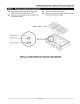
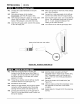
8-1 Connect the U-tube manometer to the LPG
supply line.
8-2 With electrical power to the cooktop
disconnected, open the LPGsupply valve.
8-3 Verify that the pressure is above 11 inches water
column (WC) and below 1/2PSI. Consult the
factory if the pressure is not within the limits.
8-4 Close the LPG supply valve. Connect the cooktop
to the LPG supply line.
8-5 Make sure all knobs on the front of the cooktop
are in the off position.
8-6 Connect the U-tube manometer to the left rear
burner's main orifice with 3/8" surgical tubing.
8-7 Open the LPG supply valve. Turn on the left rear
burner. The manometer should read 10 inches
WC +/- 1/2inch. Contact the factory if the
reading is not within the limits.
8-8 Turn off the burner and the gas supply valve.
Place end of tube over main orifice
7
Fiqure 8-1 Pressure Test Set-up
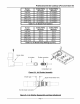
9-1 Determine the appropriate air shutter part
number for the left rear burner from Table 9-t
on page 9. Be sure to match the model number
and burner location. The shutter part number
appears on its side.
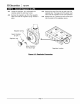
9-2 Thread the air shutter onto the left rear shutter
connector about 6 turns (see Figure 9-1).
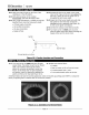
9-3 Reinstall the burner base.
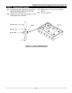
9-4 Measure the gap between the end of the shutter
connector and the opposite end of the shutter
opening with the pocket rule (see Figure 9-2).
9-5 Compare the measured gap to the gap listed in
Table 9-2 for the appropriate model number and
the burner location.
9-6 Hold the shutter connector with the 8"
adjustable wrench. Adjust the air shutter using
the 6" adjustable wrench until the gap is to
within 1/16" (1.6 mm) of the gap indicated in
the table.
9-7 Secure the shutter with thread-locker (see
Figure 9-2).
9-8 Check to make sure that the compression nut is
still tightened into the back of the shutter
connector,
9-9 Repeat steps 9-I through 9-8 for the remaining
burners.
Page 8