INSTALLATION, OPERATING AND MAINTENANCE INSTRUCTIONS ISTRUZIONI DI INSTALLAZIONE, FUNZIONAMENTO E MANUTENZIONE INSTRUCTIONS D'INSTALLATION, D'UTILISATION ET DE MAINTENANCE INSTRUCCIONES DE INSTALACIÓN, USO Y MANTENIMIENTO TAVOLI REFRIGERATI E FREEZER CON CONTROLLO ELETTRONICO REFRIGERATED AND FREEZER COUNTERS WITH ELECTRONIC CONTROL TABLES RÉFRIGÉRÉES ET FREEZERS À CONTRÔLE ÉLECTRONIQUE MESAS REFRIGERADAS Y CONGELADOR CON CONTROL ELECTRÓNICO USA IT FR ES Page Pagina Page Página 14 29 44 59 -28 -43 -58
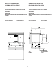
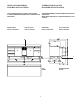
INSTALLATION DIAGRAM SCHEMA D’INSTALLAZIONE SCHÉMA D’INSTALLATION DIAGRAMA DE INSTALACIÓN TAVOLO REFRIGERATO 2 VANI CON ALZATINA 2-COMPARTMENT REFRIGERATED COUNTER WITH SHOULDER TABLE RÉFRIGÉRÉE 2 COMPARTIMENTS AVEC BORD REHAUSSÉ MESA REFRIGERADA DE 2 COMPARTIMENTOS CON COPETE TAVOLO FREEZER 2 VANI CON ALZATINA 2-COMPARTMENT FREEZER COUNTER WITH SHOULDER TABLE RÉFRIGÉRÉE 2 COMPARTIMENTS AVEC BORD REHAUSSÉ MESA CONGELADOR DE 2 COMPARTIMENTOS CON COPETE FRONT VIEW VISTA FRONTALE SIDE VIEW VISTA LATERALE
USA FR A = COMPARTIMENT MODULAIRE PRÉDISPOSÉ POUR A = MODULAR COMPARTMENT DESIGNED FOR SOLID PORTES NORMALES (CLAYETTES EN CELLULE) OU DOORS (WIRE SHELVES IN CELL) OR DRAWER UNIT BLOC TIROIRS B = MODULAR COMPARTMENT DESIGNED FOR B = COMPARTIMENT MODULAIRE PRÉDISPOSÉ POUR REFRIG ERATING UNIT OR FREEZER GROUPE FRIGORIFIQUE OU GROUPE C = OUTLET FOR DRAINING OF LIQUIDS FROM CELL, CONSERVATEUR DIAMETER 0,69"/17,5 mm.
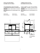
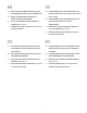
INSTALLATION DIAGRAM SCHEMA D’INSTALLAZIONE SCHÉMA D’INSTALLATION DIAGRAMA DE INSTALACIÓN TAVOLO REFRIGERATO 3 VANI CON ALZATINA 3-COMPARTMENT REFRIGERATED COUNTER WITH SHOULDER TABLE RÉFRIGÉRÉE 3 COMPARTIMENTS AVEC BORD REHAUSSÉ MESA REFRIGERADA DE 3 COMPARTIMENTOS CON COPETE TAVOLO FREEZER 3 VANI CON ALZATINA3COMPARTMENT FREEZER COUNTER WITH SHOULDER TABLE RÉFRIGÉRÉE 3 COMPARTIMENTS AVEC BORD REHAUSSÉ MESA CONGELADOR DE 3 COMPARTIMENTOS CON COPETE FRONT VIEW VISTA FRONTALE SIDE VIEW VISTA LATERALE V
USA FR A = COMPARTIMENT MODULAIRE PRÉDISPOSÉ POUR A = MODULAR COMPARTMENT DESIGNED FOR SOLID PORTES NORMALES (CLAYETTES EN CELLULE) OU DOORS (WIRE SHELVES IN CELL) OR DRAWER UNIT BLOC TIROIRS B = MODULAR COMPARTMENT DESIGNED FOR B = COMPARTIMENT MODULAIRE PRÉDISPOSÉ POUR REFRIG ERATING UNIT OR FREEZER GROUPE FRIGORIFIQUE OU GROUPE C = OUTLET FOR DRAINING OF LIQUIDS FROM CELL, CONSERVATEUR DIAMETER 0,69"/17,5 mm.
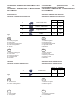
INSTALLATION DIAGRAM SCHEMA D’INSTALLAZIONE SCHÉMA D’INSTALLATION DIAGRAMA DE INSTALACIÓN TAVOLO REFRIGERATO 4 VANI CON ALZATINA 4 COMPARTMENT REFRIGERATED COUNTER WITH SHOULDER TABLE RÉFRIGÉRÉE 4 COMPARTIMENTS AVEC BORD REHAUSSÉ MESA REFRIGERADA DE 4 COMPARTIMENTOS CON COPETE FRONT VIEW VISTA FRONTALE SIDE VIEW VISTA LATERALE VUE DE FACE VISTA FRONTAL VUE LATÉRALE VISTA LATERAL B A A A A A C I C I TOP PIANO 6 VUE DE DESSUS PLANO
USA FR A = COMPARTIMENT MODULAIRE PRÉDISPOSÉ POUR A = MODULAR COMPARTMENT DESIGNED FOR SOLID PORTES NORMALES (CLAYETTES EN CELLULE) OU DOORS (WIRE SHELVES IN CELL) OR DRAWER UNIT BLOC TIROIRS B = MODULAR COMPARTMENT DESIGNED FOR B = COMPARTIMENT MODULAIRE PRÉDISPOSÉ POUR REFRIG ERATING UNIT OR FREEZER GROUPE FRIGORIFIQUE OU GROUPE C = OUTLET FOR DRAINING OF LIQUIDS FROM CELL, CONSERVATEUR DIAMETER 0,69"/17,5 mm.
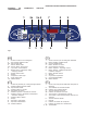
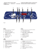
PANEL DE CONTROL VERSIÓN "FRIGORÍFICO” PANNEAU DE "RÉFRIGÉRATEUR” COMMANDE 1 2a 2 Fig.
“FREEZER” VERSION CONTROL PANEL PANNELLO DI CONTROLLO VERSIONE "CONGELATORE” 1 Fig.
CATEGORIES: TEMPERATURE AND HUMIDITY SETTING CATEGORIE: TEMPERATURA E IMPOSTAZIONE DELL'UMIDITA' CATÉGORIES: TEMPÉRATURE ET PROGRAMMATION DE L’HUMIDITÉ CATEGORÍAS: TEMPERATURA Y CONFIGURACIÓN DE LA HUMEDAD REFRIGERATOR VERSIONE A TEMPERATURA NEGATIVA VERSION À TEMPÉRATURE NÉGATIVE VERSIÓN DE TEMPERATURA NEGATIVA Fig.3 Temp.
INCORRECT DISTRIBUTION OF FOOD CARICO NON CORRETTO DEGLI ALIMENTI CHARGEMENT DES ALIMENTS INCORRECT CARGA INCORRECTA DE LOS ALIMENTOS CORRECT DISTRIBUTION OF FOOD CARICO CORRETTO DEGLI ALIMENTI CHARGEMENT DES ALIMENTS CORRECT CARGA CORRECTA DE LOS ALIMENTOS Fig.6 Fig.5 CLEANING OF THE CONDENSER PULIZIA PERIODICA DEL CONDENSATORE NETTOYAGE PÉRIODIQUE DU CONDENSEUR LIMPIEZA PERIÓDICA DEL CONDENSADOR Fig.
FUNCTIONAL SPACES SPAZI FUNZIONALI ESPACES FONCTIONNELS ESPACIOS FUNCIONALES 74.01" 1880 mm 2 67 6.3 0 m 8" m Fig.
ESEMPIO STAMPA REPORT EXAMPLE OF REPORT PRINTOUT 06:41 23:41 23:31 23:21 23:11 23:01 22:51 EXEMPLE D'IMPRESSION DE RAPPORT EJEMPLO DE IMPRESIÓN DE INFORME *** Defrost END 5 5 5 5 *** Defrost START 5 End: Start: **** POWER FAIL **** 11/03/2001 22:35 11/03/2001 22:32 22:31 22:28 time 11/03/2002 22:26 22:21 22:16 22:11 22:06 22:01 21:56 21:51 21:46 21:41 21:36 21:31 21:26 21:21 21:16 21:11 21:06 21:01 20:56 20:51 5 5 °C Tcell 22:27 5 5 5 5 5 5 5 5 5 *** Door opened OFF 5 Allarme di servizio di tipo "b
USA TABLE OF CONTENTS PRECAUTIONS ......................................................................... Page 16 A.1 GENERAL INFORMATION ........................................................ Page 17 A.1.1 Foreword ..................................................................................................................... Page 17 A.1.2 Intended use and limitations ...................................................................................... Page 17 A.1.3 Testing .............
C.1.5 Loading the product .................................................................................................... Page 23 C.1.6 Defrosting .................................................................................................................... Page 23 C.1.7 ALARMS ....................................................................................................................... Page 23 C.1.7.1 General description .........................................................
PRECAUTIONS To reduce the risk of fire, electric shock or injury during use of the appliance, follow these basic precautions, with particular attention to the following: • Read all instructions before using the appliance. • This Manual does not cover every possible condition and situation that may occur. Use common sense and caution when installing, operating and servicing this appliance.
A.1 GENERAL INFORMATION A.1.1 FOREWORD This manual provides all the information necessary for correct installation, use and maintenance of the equipment. Therefore the manual and all the technical documentation supplied must always be kept with with the appliance for possible consultation by technicians or users. It is important to inform the appliance user regarding the regulations on safety during and after installation.
2-COMPARTMENT FREEZER COUNTER WITH SHOULDER 3-COMPARTMENT REFRIGERATED COUNTER WITH SHOULDER External dimensions: - Width - Depth with door closed - Depth with door open - Depth with drawers open - Height 69.25" 27.56" 43.70" 49.99" 37.40" 1759 700 1110 1270 950 mm mm mm mm mm Compartment dimensions: - Width 14.37" - Depth 19.68" - Height 21.26" Grill dimensions 20.87"x12.79" 365 500 540 530x325 mm mm mm mm Power supply 115V single-phase 60Hz Total power Refrigerant type Qty refrigerant 0.
B.1 INSTALLATION press board: corner protection elements WEAR PROTECTIVE GLOVES WHEN UNPACKING AND INSTALLING THE APPLIANCE. B.1.2 POSITIONING Install the equipment, taking all the safety precautions required for this type of operation and respecting the relevant fire-prevention instructions. Install the appliance in a ventilated place, away from heat sources such as radiators or air-conditioning systems, to allow correct cooling of the cooling unit assembly.
If the equipment is installed in places where there are corrosive substances (chlorine, etc.), it is advisable to go over all the stainless-steel surfaces with a cloth moistened with paraffin oil in order to create a protective film. The maximum room temperature at which the appliance can operate is +109.4°F/+43°C. B.1.4 WATER CONNECTION The appliance is equipped with a drain hole for draining any liquids collected in the compartment.
C.1.2 FIRST START-UP AND TEMPERATURE ADJUSTMENT The appliance has a main ON/OFF switch. C.1 OPERATION and INSTRUCTIONS FOR THE USER Switch the appliance on by pressing the ON/OFF button: C.1.1 CONTROL PANELS (see fig. 1/2/3/4) C.1.1.
- To store the new set value, wait until it stops flashing and exit the program - To store the new set value, wait until it stops flashing and exit the program SET SET If no selection is made within 15 seconds, the last value displayed will be automatically confirmed and the display of compartment temperature will be updated. Temperature adjustment range for appliances: 2-3-4 compartment refrigerated counters Position “MIN” = 28.
- Manual defrost The defrost cycle is activated manually by holding down the top MANUAL DEFROST button for 5 seconds To select a category, press the top MANUAL DEFROST button or bottom SET button or During this function the “dEFr” light is on. SET C.1.7 ALARMS C.1.7.
buzzer: buzzer activated HACCP WHAT IS RECORDED? Press the button to display the alarm (AL1) HACCP the buzzer goes off; press again for 5 Press to display the symbol again. Press the button seconds until the alarm (AL1) is displayed. HACCP the temperature, start date and Press again HACCP next alarm for max. compartment temperature. If no button is pressed within 10 seconds the HACCP section is quitted. · CHECKING OLD ALARMS time are given in a message: “TEMP 78.8F/26C Start 17.
C.1.7.4 LIST OF SERVICE ALARMS · Type “b” service alarms b1 Door open Microswitch broken b2 Reset the HACCP memory b3 b4 C.1.7.6 RESETTING THE HACCP ALARM The system can record up to a max. of 99 compartment high temperature alarms.
C.3.2.1 Reversing the door Remove the bottom hinge fixing screws and then the door. Remove the plate on the bottom part of the door and refit it on the opposite side. Shift the top hinge to the other side, place the door on the hinge then fix the bottom hinge in the special seats arranged on the other side. C.2 HACCP CONNECTIONS (ACCESSORIES) C.2.1 Basic system connection (accessory code F880048) The printer can provide a printout of data obtained by the sensor connected to the electronic board.
C.3.3 SHELF MODULARITY To replace the shelf, remove the fixing screws located under the shelf, shift the shelf towards the front of the counter to release it from the rear seats, then lift it out. D.2 MAINTENANCE TO BE PERFORMED BY AUTHORIZED PERSONNEL ONLY Extraordinary maintenance operations must be carried out by AUTHORIZED SERVICE PERSONNEL. USE SUITABLE SAFETY EQUIPMENT (GLOVES AND MASK) WHEN CARRYING OUT ANY MAINTENANCE OPERATION. WARNING: Do not touch the equipment with wet hands or feet.
If the fault persists after carrying out the above checks, contact Technical Service, remembering to specify the following: • nature of the fault; • appliance PNC (production code); • Ser. No. (appliance serial number). Note: The code and serial number are essential for identifying the type of appliance and date of manufacture. Example: PNC 726682 - Ser.No. 62100040 726682: 2-compartment refrigerated counter with shoulder 62100040: produced in 2006, week 21, 40th piece. D.4 WASTE DISPOSAL AND DEMOLITION D.