INSTALLATION, OPERATING AND MAINTENANCE INSTRUCTIONS ISTRUZIONI DI INSTALLAZIONE, FUNZIONAMENTO E MANUTENZIONE INSTRUCTIONS D'INSTALLATION, D'UTILISATION ET DE MAINTENANCE INSTRUCCIONES DE INSTALACIÓN, USO Y MANTENIMIENTO "HEAVY DUTY SMART" VERTICAL REFRIGERATOR FRIGORIFERO VERTICALE "HEAVY DUTY SMART" RÉFRIGÉRATEUR VERTICAL "HEAVY DUTY SMART" FRIGORÍFICO VERTICAL "HEAVY DUTY SMART" USA IT FR ES Page Pagina Page Página 33 50 6886 - 49 67 85 104 DOC. NO. 5957 409 02 VERSION 3 2007.
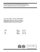
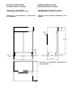
INSTALLATION DIAGRAM SCHEMA D'INSTALLAZIONE SCHÉMA D’INSTALLATION DIAGRAMA DE INSTALACIÓN 171.
C = OUTLET FOR DRAINING OF LIQUIDS FROM CHAMBER, DIAMETER 0.69 " / 17.5 mm I = POWER SUPPLY CABLE, LENGTH 137.79 " / 3500 mm, SCHUKO TYPE PLUG. C = PILETTA PER LO SCARICO LIQUIDI DELLA CELLA, DIAMETRO 0,69 " / 17,5 mm I = CAVO D'ALIMENTAZIONE LUNGHEZZA 137,79 " / 3500 mm, PRESA TIPO SCHUKO. C = BONDE POUR L’ÉVACUATION DES LIQUIDES DE LA CELLULE, DIAMÈTRE 0,69 " / 17,5 mm I = CÂBLE D’ALIMENTATION LONGUEUR 137,79 " / 3500 mm, PRISE TYPE SCHUKO.
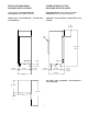
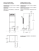
INSTALLATION DIAGRAM SCHEMA D'INSTALLAZIONE SCHÉMA D’INSTALLATION DIAGRAMA DE INSTALACIÓN 171.
I = POWER SUPPLY CABLE, LENGTH 137.79 " / 3500 mm, SCHUKO TYPE PLUG. I = CAVO D'ALIMENTAZIONE LUNGHEZZA 137,79 " / 3500 mm, PRESA TIPO SCHUKO. I = CÂBLE D’ALIMENTATION LONGUEUR 137,79 " / 3500 mm, PRISE TYPE SCHUKO. I = CABLE DE ALIMENTACIÓN de 137,79 pulg/3500 mm DE LONGITUD, ENCHUFE TIPO SCHUKO.
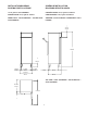
INSTALLATION DIAGRAM SCHEMA D'INSTALLAZIONE SCHÉMA D’INSTALLATION DIAGRAMA DE INSTALACIÓN 369.
C = OUTLET FOR DRAINING OF LIQUIDS FROM CHAMBER, DIAMETER 0.69 " / 17.5 mm I = POWER SUPPLY CABLE, LENGTH 137.79 " / 3500 mm, SCHUKO TYPE PLUG. C = PILETTA PER LO SCARICO LIQUIDI DELLA CELLA, DIAMETRO 0,69 " / 17,5 mm I = CAVO D'ALIMENTAZIONE LUNGHEZZA 137,79 " / 3500 mm, PRESA TIPO SCHUKO. C = BONDE POUR L’ÉVACUATION DES LIQUIDES DE LA CELLULE, DIAMÈTRE de 0,69 pulg/17,5 mm I = CÂBLE D’ALIMENTATION LONGUEUR 137,79 " / 3500 mm, PRISE TYPE SCHUKO. C = DESAGÜE DE LÍQUIDOS DE LA CÁMARA, DIÁMETRO 0,69 " / 17.
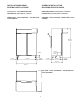
INSTALLATION DIAGRAM SCHEMA D'INSTALLAZIONE SCHÉMA D’INSTALLATION DIAGRAMA DE INSTALACIÓN 369.
I = POWER SUPPLY CABLE, LENGTH 137.79 " / 3500 mm, SCHUKO TYPE PLUG. I = CAVO D'ALIMENTAZIONE LUNGHEZZA 137,79 " / 3500 mm, PRESA TIPO SCHUKO. I = CÂBLE D’ALIMENTATION LONGUEUR 137,79 " / 3500 mm, PRISE TYPE SCHUKO. I = CABLE DE ALIMENTACIÓN de 137,79 pulg/3500 mm DE LONGITUD, ENCHUFE TIPO SCHUKO.
INSTALLATION DIAGRAM SCHEMA D'INSTALLAZIONE SCHÉMA D’INSTALLATION DIAGRAMA DE INSTALACIÓN REFRIGERATOR 171.
C = OUTLET FOR DRAINING OF LIQUIDS FROM CHAMBER, DIAMETER 0.69 " / 17.5 mm I = POWER SUPPLY CABLE, LENGTH 137.79 " / 3500 mm, SCHUKO TYPE PLUG. C = PILETTA PER LO SCARICO LIQUIDI DELLA CELLA, DIAMETRO 0,69 " / 17,5 mm I = CAVO D'ALIMENTAZIONE LUNGHEZZA 137,79 " / 3500 mm, PRESA TIPO SCHUKO. C = BONDE POUR L’ÉVACUATION DES LIQUIDES DE LA CELLULE, DIAMÈTRE 0,69 " / 17,5 mm I = CÂBLE D’ALIMENTATION LONGUEUR 137,79 " / 3500 mm, PRISE TYPE SCHUKO.
INSTALLATION DIAGRAM SCHEMA D'INSTALLAZIONE SCHÉMA D’INSTALLATION DIAGRAMA DE INSTALACIÓN REFRIGERATOR/FREEZR 171.
C = OUTLET FOR DRAINING OF LIQUIDS FROM CHAMBER, DIAMETER 0.69 " / 17.5 mm I = POWER SUPPLY CABLE, LENGTH 137.79 " / 3500 mm, SCHUKO TYPE PLUG. C = PILETTA PER LO SCARICO LIQUIDI DELLA CELLA, DIAMETRO 0,69 " / 17,5 mm I = CAVO D'ALIMENTAZIONE LUNGHEZZA 137,79 " / 3500 mm, PRESA TIPO SCHUKO. C = BONDE POUR L’ÉVACUATION DES LIQUIDES DE LA CELLULE, DIAMÈTRE 0,69 " / 17,5 mm I = CÂBLE D’ALIMENTATION LONGUEUR 137,79 " / 3500 mm, PRISE TYPE SCHUKO.
INSTALLATION DIAGRAM SCHEMA D'INSTALLAZIONE SCHÉMA D’INSTALLATION DIAGRAMA DE INSTALACIÓN REFRIGERATOR 369.
C = OUTLET FOR DRAINING OF LIQUIDS FROM CHAMBER, DIAMETER 0.69 " / 17.5 mm I = POWER SUPPLY CABLE, LENGTH 137.79 " / 3500 mm, SCHUKO TYPE PLUG. C = PILETTA PER LO SCARICO LIQUIDI DELLA CELLA, DIAMETRO 0,69 " / 17,5 mm I = CAVO D'ALIMENTAZIONE LUNGHEZZA 137,79 " / 3500 mm, PRESA TIPO SCHUKO. C = BONDE POUR L’ÉVACUATION DES LIQUIDES DE LA CELLULE, DIAMÈTRE 0,69 " / 17,5 mm I = CÂBLE D’ALIMENTATION LONGUEUR 137,79 " / 3500 mm, PRISE TYPE SCHUKO.
INSTALLATION DIAGRAM SCHEMA D'INSTALLAZIONE SCHÉMA D’INSTALLATION DIAGRAMA DE INSTALACIÓN REFRIGERATOR/FREEZER 369.
C = OUTLET FOR DRAINING OF LIQUIDS FROM CHAMBER, DIAMETER 0.69 " / 17.5 mm I = POWER SUPPLY CABLE, LENGTH 137.79 " / 3500 mm, SCHUKO TYPE PLUG. C = PILETTA PER LO SCARICO LIQUIDI DELLA CELLA, DIAMETRO 0,69 " / 17,5 mm I = CAVO D'ALIMENTAZIONE LUNGHEZZA 137,79 " / 3500 mm, PRESA TIPO SCHUKO. C = BONDE POUR L’ÉVACUATION DES LIQUIDES DE LA CELLULE, DIAMÈTRE 0,69 " / 17,5 mm I = CÂBLE D’ALIMENTATION LONGUEUR 137,79 " / 3500 mm, PRISE TYPE SCHUKO.
INSTALLATION DIAGRAM SCHEMA D'INSTALLAZIONE SCHÉMA D’INSTALLATION DIAGRAMA DE INSTALACIÓN FISH REFRIGERATOR 369.
C = OUTLET FOR DRAINING OF LIQUIDS FROM CHAMBER, DIAMETER 0.69 " / 17.5 mm I = POWER SUPPLY CABLE, LENGTH 137.79 " / 3500 mm, SCHUKO TYPE PLUG. C = PILETTA PER LO SCARICO LIQUIDI DELLA CELLA, DIAMETRO 0,69 " / 17,5 mm I = CAVO D'ALIMENTAZIONE LUNGHEZZA 137,79 " / 3500 mm, PRESA TIPO SCHUKO. C = BONDE POUR L’ÉVACUATION DES LIQUIDES DE LA CELLULE, DIAMÈTRE 0,69 " / 17,5 mm I = CÂBLE D’ALIMENTATION LONGUEUR 137,79 " / 3500 mm, PRISE TYPE SCHUKO.
INSTALLATION DIAGRAM SCHEMA D'INSTALLAZIONE SCHÉMA D’INSTALLATION DIAGRAMA DE INSTALACIÓN REFRIGERATOR/FREEZER 369.
C = OUTLET FOR DRAINING OF LIQUIDS FROM CHAMBER, DIAMETER 0.69 " / 17.5 mm I = POWER SUPPLY CABLE, LENGTH 137.79 " / 3500 mm, SCHUKO TYPE PLUG. C = PILETTA PER LO SCARICO LIQUIDI DELLA CELLA, DIAMETRO 0,69 " / 17,5 mm I = CAVO D'ALIMENTAZIONE LUNGHEZZA 137,79 " / 3500 mm, PRESA TIPO SCHUKO. C = BONDE POUR L’ÉVACUATION DES LIQUIDES DE LA CELLULE, DIAMÈTRE 0,69 " / 17,5 mm I = CÂBLE D’ALIMENTATION LONGUEUR 137,79 " / 3500 mm, PRISE TYPE SCHUKO.
SCHÉMA DE MISE EN PLACE DES TUYAUX POUR GROUPE À DISTANCE, VALABLE POUR LES ARMOIRES PRÉDISPOSÉES POUR GROUPE À DISTANCE 550/650 OU POUR LES ARMOIRES 1200/1400 À DEUX TEMPÉRATURES PRÉDISPOSÉES POUR GROUPE À DISTANCE DIAGRAM FOR POSITIONING OF PIPES FOR REMOTE UNIT; APPLICABLE FOR REMOTE CABINETS 550/650 OR FOR REMOTE CABINETS 1200/1400 WITH TWO TEMPERATURES SCHEMA POSIZIONAMENTO DEI TUBI PER GRUPPO REMOTO, VALIDO PER ARMADI REMOTI 550/650 OPPURE PER ARMADI REMOTI 1200/1400 A DUE TEMPERATURE ESQUEMA DE POS
DIAGRAM FOR POSITIONING OF PIPES FOR REMOTE UNIT; APPLICABLE FOR REMOTE CABINETS 550/650 WITH TWO TEMPERATURES OR FOR CABINETS 1200/1400 WITH SMALL CELL (COMPARTMENT 350) SCHÉMA DE MISE EN PLACE DES TUYAUX POUR GROUPE À DISTANCE, VALABLE POUR LES ARMOIRES 550/650 À DEUX TEMPÉRATURES OU POUR LES ARMOIRES 1200/ 1400 AVEC PETITE CELLULE (COMPARTIMENT 350) SCHEMA POSIZIONAMENTO DEI TUBI PER GRUPPO REMOTO VALIDO PER ARMADI 550/650 A DUE TEMPERATURE OPPURE PER ARMADI 1200/1400 CON CELLETTA (VANO 350) ESQUEMA D
DIAGRAM FOR POSITIONING OF PIPES FOR REMOTE UNIT; APPLICABLE FOR CABINETS 1200/1400 SCHÉMA DE MISE EN PLACE DES TUYAUX POUR GROUPE À SCHEMA POSIZIONAMENTO DEI TUBI PER GRUPPO REMOTO VALIDO PER ARMADI 1200/1400 ESQUEMA DE MONTAJE DE LOS TUBOS PARA GRUPO REMOTO, VÁLIDO PARA ARMARIOS 1200/1400 ESQUEMA DE POSICIONAMENTO DOS TUBOS PARA GRUPO REMOTO VÁLIDO PARA ARMÁRIOS 1200/1400 DISTANCE, VALABLE POUR LES ARMOIRES 1200/1400 B A A = SUCTION PIPE OUTSIDE DIAMETER 6 mm B = DELIVERY PIPE OUTSIDE DIAMETER 10 mm
“REFRIGERATOR” VERSION CONTROL PANEL PANNELLO DI CONTROLLO VERSIONE "FRIGORIFERO” 1 PANNEAU DE COMMANDE VERSION RÉFRIGÉRATEUR” PANEL DE CONTROL DE REFRIGERADOR 2a 3a 4 7 8 MANUAL DEFROST 9 COMPRESSOR STATUS POWER SUPPLY STATUS 1 2 3 CATEGORY 4 ACCESS TO FOOD CATEGORIES % SET HUM HIGH HIGH HUM. ON/OFF SERVICE ALARMS HACCP TEMPERATURE/ CATEGORY SELECTION HACCP ALARMS PRINT POWER ON/OFF 7 DAYS REPORT Fig.
“FREEZER” VERSION CONTROL PANEL PANNELLO DI CONTROLLO VERSIONE "CONGELATORE” PANNEAU DE COMMANDE VERSION “CONGÉLATEUR” PANEL DE CONTROL DE CONGELADOR 1 2a 3 6 7 MANUAL DEFROST 8 COMPRESSOR STATUS POWER SUPPLY STATUS 1 2 SET CATEGORY ACCESS TO FOOD CATEGORIES SERVICE ALARMS HACCP TEMPERATURE/ CATEGORY SELECTION HACCP ALARMS PRINT POWER ON/OFF 7 DAYS REPORT Fig.
CONTROL PANEL "2-TEMPERATURE REFRIGERATOR" VERSION PANNELLO DI CONTROLLO VERSIONE "FRIGORIFERO 2 TEMPERATURE” 2a 3a 4 1 7 8 MANUAL DEFROST PANNEAU DE COMMANDE VERSION "RÉFRIGÉRATEUR À 2 TEMPÉRATURES" PANEL DE CONTROL DE "FRIGORÍFICO DE 2 TEMPERATURAS” 9 COMPRESSOR STATUS POWER SUPPLY STATUS 7 8 MANUAL DEFROST 1 9 COMPRESSOR STATUS POWER SUPPLY STATUS 1 2 3 2a 3a 4 1 2 % CATEGORY 4 ACCESS TO FOOD CATEGORIES SET HUM HIGH HIGH HUM.
PANNEAU DE COMMANDE VERSION "RÉFRIGÉRATEUR/ CONGÉLATEUR À 2 TEMPÉRATURES" PANEL DE CONTROL DE "FRIGORÍFICO/CONGELADOR DE 2 TEMPERATURAS” CONTROL PANEL "2-TEMPERATURE REFRIGERATOR/ FREEZER" VERSION PANNELLO DI CONTROLLO VERSIONE "FRIGORIFERO/ CONGELATORE 2 TEMPERATURE” Fare riferimento alla pag. 24 MANUAL DEFROST 1 COMPRESSOR STATUS 6 7 MANUAL DEFROST POWER SUPPLY STATUS 1 8 COMPRESSOR STATUS POWER SUPPLY STATUS 1 2 3 2a 3 CATEGORY 4 ACCESS TO FOOD CATEGORIES % SET HUM HIGH HIGH HUM.
REVERSING OPENING OF THE DOORS INVERSIONE APERTURA DELLE PORTE INVERSION DU SENS D’OUVERTURE DES PORTES CAMBIO DE DIRECCIÓN DE APERTURA DE LAS PUERTAS Fig.
REVERSING OPENING OF HALF DOORS INVERSIONE APERTURA DELLE MEZZE PORTE INVERSION DU SENS D'OUVERTURE DES DEMI-PORTES INVERSIÓN DEL SENTIDO DE APERTURA DE LAS MEDIAS PUERTAS Fig.
INCORRECT DISTRIBUTION OF FOOD CARICO NON CORRETTO DEGLI ALIMENTI CHARGEMENT DES ALIMENTS INCORRECT CARGA INCORRECTA DE LOS ALIMENTOS CORRECT DISTRIBUTION OF FOOD CARICO CORRETTO DEGLI ALIMENTI CHARGEMENT DES ALIMENTS CORRECT CARGA CORRECTA DE LOS ALIMENTOS Fig.7 Fig.
Questa pagina e' stata lasciata in bianco intenzionalmente This page has been intentionally left blank Cette page est intentionnellement laissée blanche Diese Seite wurde absichtlich leer gelassen Esta página ha sido dejada en blanco de manera intencional Denna sida har avsiktligt lämnats tom Tämä sivu on tarkoituksella tyhjä Denne side er med vilje efterladt blank Denne siden er med hensikt blank 32
USA TABLE OF CONTENTS SAFETY INSTRUCTIONS ......................................................... Page 35 A.1 GENERAL INFORMATION........................................................ Page 36 A.1.1 Foreword ..................................................................................................................... Page 36 A.1.2 Intended use and limitations ...................................................................................... Page 36 A.1.3 Testing ........................
C.1.5 Loading the product .................................................................................................... Page 45 C.1.6 Defrosting .................................................................................................................... Page 46 C.1.7 Alarms ......................................................................................................................... Page 46 C.1.7.1 General description ..........................................................
SAFETY INSTRUCTIONS To reduce the risk of fire, electrical shock, or injury when using your appliance, please follow these basic precautions, particularly the following: • Read all instructions before using your appliance. • This manual does not cover every possible condition and situation that may occur. Use common sense and caution when installing, operating and maintaining this appliance.
A.1 GENERAL INFORMATION A.1.6 DATA PLATE POSITION The data plate with all the appliance specifications is located on the refrigeration unit compartment at the top right hand side. There is also a plate bearing the appliance’s PNC code and serial number located underneath the logo. A.1.1 FOREWORD The purpose of this manual is to provide the necessary information for the correct installation, operation, use and maintenance of the appliance.
(²) ASHRAE PERFORMANCE: room temperature 89.6°F/ +32°C, dew point 129.92°F/+54.4°C and evaporation temperature 44.96°F/+7.2°C. (*) Automatic (by means of electronic board) +32°C, dew point 129.92°F/+54.4°C and evaporation temperature 44.96°F/+7.2°C. (*) Automatic (by means of electronic board) Freezer model 369.84 gallons / 1400 litres 369.84 gallons Gross capacity External dimensions: - Width 23.62" - Depth with door closed 26.18" - Depth with door open 47.24" - Height 83.15" Freezer model 171.
+32°C, dew point 129.92°F/+54.4°C and evaporation temperature 44.96°F/+7.2°C. (*) Automatic (by means of electronic board) (°) At room temperature 104°F/40°C. (¹) At room temperature 89.6°F/32°C, dew point 131°F/+55°C and evaporation temperature 14°F/- 10°C. (²) ASHRAE PERFORMANCE : room temperature 89.6°F/ +32°C, dew point 129.92°F/+54.4°C and evaporation temperature 44.96°F/+7.2°C. (*) Automatic (by means of electronic board) Refrigerator/freezer model 171.
Max. room temp. +109.4°F +43°C Total current absorbed (°) 12 A Type of refrigerant R134a R134a Refrigerant charge 0.595 lbs/0.529 lbs 270 g/240 g Refrigerant capacity(¹) 526 W 396 W Refrigerant capacity(²) 1137 W 841 W Defrost power 450 W 450 W No. and type of defrosts (*)min. 1 every 24 hours x max. 30' Freezer model 171.71 gallons / 650 litres, remote unit (1 door, 2 ½ doors) (°) At room temperature 104°F/40°C. (¹) At room temperature 89.
Refrigerator model 369.84 gallons / 1400 litres, remote unit, (2 doors, 4 ½ doors) Gross capacity 369.84 gallons 1400 litres External dimensions: - Width 23.62" 600 mm - Depth with door closed 26.18" 665 mm - Depth with door open 47.24" 1200 mm - Height 83.15" 2112 mm Freezer model 369.84 gallons / 1400 litres, remote unit, (2 doors, 4 ½ doors) Gross capacity 369.84 gallons 1400 litres External dimensions: - Width 23.62" 600 mm - Depth with door closed 26.18" 665 mm - Depth with door open 47.
Refrigerator/freezer model 369.84 gallons / 1400 litres 1 door + 2 ½ doors 2 temperatures ("energy saving") Gross capacity 369.84 gallons 1400 litres External dimensions: - Width 59.05" 1500 mm - Depth with door closed 31.89" 810 mm - Depth with door open 57.60" 1463 mm - Height 80.71" 2112 mm B.1 INSTALLATION WEAR PROTECTIVE GLOVES WHEN UNPACKING AND INSTALLING THE APPLIANCE. Read these instructions carefully before attempting installation.
pressed board: protective surround elements B.1.2 POSITIONING Install the equipment, taking all the safety precautions required for this type of operation, also respecting the relevant fire-prevention instructions. Place the appliance in a ventilated room and away from heat sources such as radiators or air-conditioning systems, in order to allow the cooling of the refrigerating unit components.
Note: After carrying out the above operations, close the holes on the unit with the special plastic caps. C.1 OPERATIONS and USER INSTRUCTIONS B.1.5 ELECTRICAL CONNECTION When making the electrical connection, carefully comply with the information on the dataplate. The appliance works on 120V/1ph/60Hz. C.1.1 CONTROL PANELS (refer to fig.1/2/3/4) C.1.1.
To set the chamber temperature, follow these steps: - press and hold SET/DOWN button for 5 seconds, Example of setting: - switch on the appliance SET the SET TEMPERATURE value appears on the display - confirm the set temperature SET the Unit of Measure Indicator light starts flashing.
171.71 gallons/650 lt and 369.84 gallons/1400 lt Freezer models Position “MIN” = -8°F / -22°C Position “MAX” = 9°F / -13°C once selected, if a selection is not made after 5 seconds, the last category displayed will be confirmed automatically and stored. C.1.3 STORAGE USING CATEGORIES BUTTON By selecting the “CATEGORY” of food to be preserved, the appliance creates the right balance between temperature and humidity in the chamber for optimum preservation of the particular product stored. C.1.
HOW TO CHECK IT? C.1.6 DEFROSTING - Automatic defrosting The appliance is equipped with an automatic defrost function. This function is indicated by the “dEFr” indicator light. Defrost water is routed to a bowl, from where it evaporates automatically. display: rolling label i.e. “TEMP 78.
- Start time and date (starting date and time of alarm) - End time and date (ending date and time of alarm) display shows “----”. C.1.7.4 SERVICE ALARMS LIST · Type “b” service alarms HACCP Press button to return to see the symbol of the b1 Door is open Microswitch is broken b2 Reset HACCP memory HACCP button to display the next alarm (AL1). Press b3 maximum chamber temperature alarm. If nothing is pressed within 10 seconds we exit from HACCP section.
C.1.7.6 HACCP ALARM RESET The maximum number of high chamber temperature alarms recordable is 99. Whenever the memory is full and a “b2” alarm occurs or at the end of the year, it is necessary to reset the memory in the following way: D.1 ROUTINE MAINTENANCE Routine maintenance tasks can be performed by non-specialised personnel. When performing maintenance please follow the instructions closely, and take great care to. The manufacturer declines any responsibility for injury sustained from unsafe acts.
D.2 MAINTENANCE TO BE PERFORMED BY TRAINED PERSONNEL ONLY Non-routine maintenance tasks must be performed by an AUTHORIZED SERVICE AGENT. USE APPROPRIATE SAFETY GEAR (GLOVES AND MASK) WHEN CARRYING OUT ANY MAINTENANCE OPERATION. ATTENTION: do not touch the appliance if hands and/or feet are wet. Before performing any cleaning or maintenance disconnect the appliance from the electrical source and carefully unplug the appliance. Do not remove safety guards. Wear protective gloves when cleaning the condenser.