INSTALLATION, OPERATING AND MAINTENANCE INSTRUCTIONS ISTRUZIONI DI INSTALLAZIONE, FUNZIONAMENTO E MANUTENZIONE INSTRUCTIONS D'INSTALLATION, D'UTILISATION ET DE MAINTENANCE INSTRUCCIONES DE INSTALACIÓN, USO Y MANTENIMIENTO "ROLL-IN SMART" ELECTRONIC CONTROL CONTROLLO ELETTRONIC0 "ROLL-IN SMART" CONTRÔLE ÉLECTRONIQUE "ROLL-IN SMART" CONTROL ELECTRÓNICO DEL "ROLL-IN SMART" USA IT FR ES Page Pagina Page Página 07 20 33 45 - 19 - 32 - 45 - 58 PART NO. 5957 411 01 VERSION 2 2005.
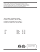
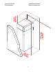
INSTALLATION DIAGRAM SCHEMA DI INSTALLAZIONE SCHÉMA D'INSTALLATION DIAGRAMA DE INSTALACIÓN FRONT VIEW VISTA FRONTALE SIDE VIEW VISTA LATERALE VUE DE FACE VISTA FRONTAL VUE DE CÔTÉ VISTA LATERAL 38 25/64" 29 17/32" 975 mm 750 mm 12 13/32" 315 mm I 83 5/64" 2110 mm 3 11/32" 85 mm 2 61/62" 23 5/8" 2 61/62" 75 mm 600 mm 75 mm 30 5/16" 770 mm Z 34 1/4" 870 mm 65 23/64" 1660 mm 1 31/32" 50 mm 24 51/64" 630 mm I = electrical connection Z = bolt holes for floor fastening I = connessione elett
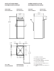
INVERSION DU SENS D'OUVERTURE DE LA PORTE CAMBIO DE DIRECCIÓN DE APERTURA DE LA PUERTA REVERSING OPENING OF THE DOOR INVERSIONE APERTURA DELLE PORTE G H Dett.1 F L E Dett.3 Dett.
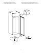
CONTROL PANEL PANNELLO COMANDI PANNEAU DE COMMANDE PANEL DE CONTROL 1 2a 3a 4 7 8 MANUAL DEFROST 9 COMPRESSOR STATUS POWER SUPPLY STATUS 1 2 3 CATEGORY 4 ACCESS TO FOOD CATEGORIES % SET HACCP HUM HIGH HIGH HUM.
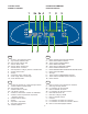
ESPACES FONCTIONNELS ESPACIOS FUNCIONALES 19.68 " 500 mm FUNCTIONAL SPACES SPAZI FUNZIONALI 102.75 " 2610 mm 3 77 0.
This page has been intentionally left blank Questa pagina e' stata lasciata in bianco intenzionalmente Cette page est intentionnellement laissée blanche Esta página ha sido dejada en blanco de manera intencional 6
USA TABLE OF CONTENTS SAFETY INSTRUCTIONS ......................................................... Page 9 A.1 GENERAL INFORMATION........................................................ Page 10 A.1.1 Foreword ..................................................................................................................... Page 10 A.1.2 Intended use and limitations ...................................................................................... Page 10 A.1.3 Testing .........................
C.1.6 Defrosting .................................................................................................................... Page 15 C.1.7 Alarms ......................................................................................................................... Page 15 C.1.7.1 General description ..................................................................................................... Page 15 C.1.7.2 HACCP .......................................................................
SAFETY INSTRUCTIONS To reduce the risk of fire, electrical shock, or injury when using your appliance, please follow these basic precautions including the following: • Read all instructions before using your appliance. • This Manual does not cover every possible condition and situation that may occur. Use common sense and caution when installing, operating and maintaining this appliance.
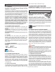
serial number located underneath the logo. A.1 GENERAL INFORMATION A.1.7 PHYSICAL SAFETY FEATURES, HAZARDS The appliance has no sharp or projecting parts. DANGER! DO NOT REMOVE. There are guards on the units to prevent access to components which require air movement. A.1.1 FOREWORD The purpose of this manual is to provide the necessary information for the correct installation, operation, use and maintenance of the appliance.
WARNING: during handling do not push or pull the unit: it may tip over or be damaged. B.1.2.2 Disposing of the packing Packing materials should be disposed of accordance with the binding laws in the country where the appliance is to be used. Recyclable plastic parts are marked as follows: polythene:outer wrapping, instructions booklet bag PE polypropylene: straps PP polystyrene foam: protective surround elements B.2.3 PHYSICAL SAFETY FEATURES, HAZARDS The appliance has no sharp or projecting parts.
tric supply line for the appliance. It is recommended that this switch/circuit breaker have lockout/tagout capability. Before making any electrical connections to this appliance, check that the power supply is adequate for the voltage, amperage, and phase requirements on the rating plate. The customer also must provide a grounded electrical line cord of suitable capacity for the input specified on the data plate.
B.2.7 CHECKING HINGES Have the hinges of the appliance checked every two years by a technician. If necessary, adjust and grease the hinges. C.1 OPERATIONS and USER INSTRUCTIONS the Unit of Measure Indicator light starts flashing. - To change the SET temperature, press SET/DOWN button or MANUAL DEFROST/UP button within 15 seconds C.1.1 CONTROL PANEL 2a 3a 4 1 7 8 9 SET MANUAL DEFROST COMPRESSOR STATUS POWER SUPPLY STATUS 1 2 3 CATEGORY 4 ACCESS TO FOOD CATEGORIES % SET HUM HIGH HIGH HUM.
Keeping button pressed down will display the selected category; - confirm the set temperature SET 2 1 2 3 CATEGORY 4 - press SET/DOWN button or MANUAL DEFROST/UP button temperature if “NONE” is displayed, this means that the function is disabled.
The SERVICE ALARMS stores and manages all the alarms available in the electronic board (except the “chamber high temperature” alarm). C.1.5 LOADING THE PRODUCT Food must be evenly distributed inside the chamber (away from the door and back wall) in order to allow proper circulation of air. C.1.7.
b) the alarm has occured press 77˚/25˚ Temperature ˚F/˚C . 68˚/20˚ · HOW LONG ARE THE ALARMS RECORDED? Forever, or better, until the memory is out of space (maximum number of recorded alarms: 99). 59˚/15˚ 50˚/10˚ Critical temperature time 41˚/5˚ 16:00 17:00 18:00 19:00 20:00 21:00 22:00 C.1.7.
· Type “E” service alarms · keep pressed together RES E1 Sensor short-circuited E2 Sensor is broken or disconnected E3 Sensor short-circuited E4 Sensor is broken or disconnected E5 Sensor short-circuited E6 Sensor is broken or disconnected E7 Sensor short-circuited E8 Sensor is broken or disconnected E9 Low chamber temperature E10 Low evaporator temperature SET until the display shows “RES”. C.1.7.
D.1 ROUTINE MAINTENANCE D.2 MAINTENANCE TO BE PERFORMED BY TRAINED PERSONNEL ONLY Routine maintenance tasks can be performed by non-specialised personnel. When performing maintenance please follow the instructions closely, keeping safe at all times. The manufacturer declines any responsibility for injury sustained from unsafe acts. Non-routine maintenance tasks must be performed by an AUTHORIZED SERVICE AGENT. USE APPROPRIATE SAFETY GEAR (GLOVES AND MASK) WHEN CARRYING OUT ANY MAINTENANCE OPERATION.
Example: PNC 726377 00 - Ser.No. 44600010 726377 00: Prostore Smart 44600010: manufactured in 2004, week 46, 10th item. D.3 HACCP CONNECTIONS (ACCESSORIES) D.5 WASTE DISPOSAL AND DEMOLITION D.3.1 HACCP CONNECTIONS Refer to the handbook enclosed with the kit for instructions on installing the accessories. Basic system connection The printer can provide a print-out of data collected by the probe connected to the electronic board.