Installation manual Tumble dryers T4250, T4350 Type N2... Selecta Control Installation manual in original language 487 05 43 61/EN 2010.06.
Contents Contents The front of the dryer.............................................................................. 4 Safety precautions.................................................................................. 5 Technical data......................................................................................... 7 Setup..................................................................................................... 11 Unpacking..............................................................
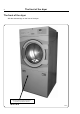
The front of the dryer 4 The front of the dryer Affix the enclosed sign on the front of the dryer CAUTION! Remove clothes from dryer as soon as it stops. This keeps wrinkles from setting in and reduces the possibility of spontaneous combustion 487 01 29 00.
Safety Precautions Safety Precautions Do not dry unwashed items in the machine The machine is not to be used if industrial chemicals have been used for cleaning. Do not allow minors to use the machine. Do not hose down the machine with water. The machine's door lock must under no circumstances be bypassed.
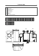
Technical data (a) (b) 1 2 3 4 5 6 7 7 Electric and gas heating Steam heating Door opening = Ø 580 Operating panel Electric connection Gas connection Steam: in Steam: out Pipe connection, evacuation A B (a) B (b) C D E F G H J K L M N O T4250 790 900 1100 1720 860 790 155 170 1505 100 1565 80 395 755 585 T4350 790 1120 1320 1720 860 790 155 170 1505 100 1565 80 395 755 585 P (a) P (b) Q T4250 1620 1820 740 T4350 1860 2040 740 (a) B (b) B (a) A (b) L J M 3 4
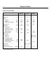
Technical data 8 Technical data T4250 Electric Gas Steam litres 250 250 250 kg 161 161 176 mm mm rpm 760 550 45 760 550 45 760 550 45 kg 12.5 12.5 12.5 kW 9/13.5 13.
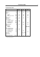
Technical data 9 Technical data T4350 Electric Gas Steam litres 349 349 349 kg 169 169 184 mm mm rpm 760 770 45 760 770 45 760 770 45 kg 17.5 17.5 17.5 kW 13.5/18 21 * m3/h m3/h m3/h m3/h 600 1000 - 1000 - 1000 Ø 200 200 200 - - ISO 7/1-R1 ISO 7/1-R1 520 270 - 270 - 270 Gas piping - ISO 7/1-R1/2 - Gas pressure - ** - < 70 < 70 < 70 Drum volume Weight net Drum diameter depth revolutions per minute Capacity, max Heat effect Air consumption Heat effect 13.
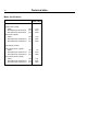
Technical data 10 Motor specifications T4250, T4350 Dryer with reversal Blower motor 3-phase Effect Revolutions per minute 50 Hz Revolutions per minute 60 Hz kW rpm rpm 0.75 2700 3200 Drum motor 3-phase Effect Revolutions per minute 50 Hz Revolutions per minute 60 Hz kW rpm rpm 0.52 2700 3300 Drum / blower motor 1-phase Effect Revolutions per minute 50 Hz Revolutions per minute 60 Hz kW rpm rpm 1.
Setup Setup 11 1 When unpacking the machine, handle it with care. The drum has no transport clamps. 500 mm Unpacking A Fastened to the pallet The dryer is fastened to the pallet by two bolts. Open the filter drawer and then remove the front bolt. A Remove the back plate and then remove the back bolt. Tumbler type 4250 1 Tumbler type 4350 From factory the dryer is equipped with 4 supporting feet (a). Positioning 1 Min.150 mm From factory the dryer is equipped with 4 supporting feet (a).
Installation Installation 13 1 Mechanical installation Dryer type 4250 1 Adjust the dryer to ensure that it is horizontal and stands firmly on all six feet. The maximum height adjustment of the feet is 15 mm. Dryer type 4350 Adjust the dryer to ensure that it is horizontal and stands firmly on all 4 feet. The maximum height adjustment of the feet is 15 mm. The feet must be locked Bearing in mind the stability of the feet, it is important to lock the tumble dryer’s feet with nuts A.
Installation 14 Up to machine No. T4250 T4350 –4250/101239 –4350/100824 2 Reversing door The loading door is reversible if it does not open to the desired side. Reversing B 1. Disconnect the power supply to the dryer. B 2. Open the operating panel. 3. Demount the filter door. 4. Unscrew the door and the front panel. 5. Unscrew the cover plate. 6. Demount the micro switch with fittings. 7. Squeeze out the black strip which is mounted in the back plate of the component unit 8.
Installation Test the door 1. Connect the power supply. 15 4 2. Start the tumble dryer. 3. If the dryer does not start when the door is 4 closed, adjust the door pin A. 4. Check that the micro switch on the door works correctly: The drum, ventilator and heat should stop when the front door is opened max. 40 mm.
Installation 16 From machine No. T4250 T4350 4250/101240– 4350/100825– 5 Reversing door The loading door is reversible if it does not open to the desired side. Reversing B 1. Disconnect the power supply to the dryer. 2. Open the operating panel. B 3. Demount the filter door. 4. Unscrew the door and the front panel. 5. Unscrew the cover plate. 6. Demount the magnetic switch with fittings. 7. Squeeze out the black strip which is mounted in the back plate of the component unit 8.
Installation Test run Check for proper operation of the door switch, as follows: 4 1. Re-connect the power supply to the dryer 2. Attempt to start the dryer with the door open. It must not start. 3. Close the door and start the machine. Open the door. The dryer must stop. If the dryer starts with the door open, or fails to stop when the door is opened during operation, repair or replace the door switch, as necessary.
Installation 18 Installation on board a ship The four accompanying fittings are fastened to the foundation by means of 4 x M10 set screws.
Installation Evacuation system 19 7 Air principle 7 The ventilator creates low pressure in the dryer, drawing air into the drum via the heating unit. The heated air passes through the garments and the drum vents. Then the air flows out through a lint filter positioned immediately in front of the ventilator. After this, the air is evacuated through the ventilator and evacuation system. It is very important that the dryer gets enough fresh air, see next section.
Installation 20 Exhaust duct • The exhaust duct must be smooth on the inside (low air resistance). • The exhaust duct must lead to the outdoors. • The exhaust duct must lead clear of the building as condensation may cause frost damage to the building. • The exhaust duct must be protected against rain and foreign objects. 10 • The exhaust duct must have gentle bends. • The exhaust duct must not be a shared duct between dryers and appliances using gas or other fuels as their energy source.
Installation 21 Gentle bends 10 W00049 Several dryers share an exhaust duct 11 W00052
Installation 22 Outlet dimensioning It is important that the dryer has the correct air volume compared to each dryer’s effect. If the air volume is smaller or larger this will result in a longer drying period. Table with air volume and dryer effect Minimum air volume If the outlet air volume gets below the minimum air volume the microprocessor will report an error and error code E15 will be displayed. Type Effect Minimum Optimum kW air volume m3/h air volume m3/h 4250 6/9 260 360 4250 13.
Installation 23 Diagram with pressure drop curve type T4250 / T4350 12 Y = Pa 700 600 500 400 50Hz 300 200 100 0 0 200 400 600 800 X = Air consumption Y = Counter-pressure Service organisation/dealer If you have questions relating to the design of the exhaust system, please contact your local dealer or service organisation.
Installation 24 Adjusting the dryer The dryer is adjusted by dismounting the back plate and measuring the static pressure behind the fan. 13 13 Drill a ø3.3mm hole A if there is not already one. The measuring is done on a no-heat program, without clothes in the dryer and with the back plate being dismounted. 120 By opening / closing the damper B the static pressure at A is either lowered or raised.
Installation Steam installation 25 14 Before start The steam pipe must be cut off and must not be under pressure. Steam a b 5 Steam 3-10 bar absolute pressure (130- 180°C). Steam forward 14 1. The branch pipe’s branch must be located at the top of the main steam pipe to prevent condensation in the steam. 2. The branch pipe must have a descending gradient and must end at a height above the inlet connecting branch (5). For measurements M, N and O, please see dimension sketch page 7. 3.
Installation 26 Steam-heated dryer 15 Mounting steam calorifier on dryer Dryer type 4250: The steam calorifier is on the pallet. Dryer type 4350: The steam calorifier is in the drum. 1. Unpack the calorifier. 15 2. Demount top back plate on the dryer. 3. Demount supporting rail on the dryer, see arrow (note which way the supporting rail turns as it has to be remounted the same way, see step 5). 4. Hang the calorifier on the bottom supporting rail on the dryer. 5.
Installation Leak test 1. Leak test the system. 2. Clean the dirt collectors (b), see the previous page. Function check The function check is described in the back of this manual. Pipe insulation All pipes must be insulated in order to reduce risk of burning. Insulation also reduces loss of heat to the surroundings.
Installation Gas installation To be carried out by qualified personnel Mount a shut-off valve upstream from the dryer. The gas connection to the dryer should be dimensioned to an output of 13.5 kW / 21 kW dependent upon the kW-rating of the dryer. The factory nozzle pressure setting corresponds to the fuel value given on the name plate. Check that the nozzle pressure and fuel value agree with the values given in the table. If not, contact the supplier. Bleed the pipe system before connecting the dryer.
Installation 30 Converting instructions to another gas type Before installing the dryer affix the label "Read the user instructions" to the inside of the door, see pictures below. The label must have the correct country code - choose the correct label from the kit. 80 mm GB, IE NL Read the technical instructions before installing the appliance. Lees de technishe instructies zorgvuldig door voordat u het apparaat installeert.
Installation 31 Table of pressure and adjustment This gas appliance has been build to run on natural gas group I2H and I2E(LL), commonly identified by GNH. The data label shows the injector size and the injector pressure and the countries that use this gas quality: DK, NO, SE, FI, CH, CZ, EE, LT, SL, TR, BG, RO, GB, ES, GR, IE, IT, PT, AT, LV, HU, IS, SK, DE, PL, LU and non-European countries. Before connecting the appliance please make sure that the supplied gas type is correct.
Installation 32 Conversion instructions - T4250 only: 1. Disconnect the power to the dryer. 3 2. Remove the back plate. 3. Remove nozzle. 4. Mount the enclosed nozzle (1), see Fig. 3. 5. Loosen the measuring branch screw (2) 1/4 turn; connect a manometer to the measuring branch (2), see Fig. 3. 6. Connect the power and select a programme with heat. 7. Start the dryer. 2 4+3 8. See nozzle pressure in table on the previous page Fig.
Installation Conversion instructions - T4350 only: 1. Disconnect the power to the dryer. 33 4 2. Remove the back plate. 3. Remove the screw on the side of the locking plate x, see Fig. 5. 4. Pull out the locking plate x, this releases the gas pipe, see Fig. 5. 5. Remove the nozzle. 6. Turn the pipe a little and mount the supplied gas nozzle, see Fig. 2. 7. Push pipe with new nozzle back into its place. 2 4+3 8. Push locking plate all the way in and tighten the screw. 9.
Installation 34 When the dryer is to be converted to another gas type, the data label on the rear of the dryer must be updated in order for the data to be correct. Place the data label enclosed in the conversion kit on top of the data label as shown below, see Fig. 7. For data label no. see Fig. 1 - T4250 or Fig. 2 - T4350.
Installation Electric installation - electric/gas/ steamheated 35 1 L1 L2 L3 N To be carried out by qualified personnel The tumble dryer must be connected to its own fuse group and pulti-pole main switch according to IEC 60947. Connecting the cable 1 Demount the cover plate from the supply unit. The cable is led through the cable gland to the terminal block and connected as illustrated.
Installation 36 Heat effect: Type 4250 = 6 k W / 9 kW / 13.5 kW Heat effect: Type 4350 = 13.5 kW / 18 kW Heating alternative Voltage alternative El heating Gas heating Steam heating Heat effect kW Motor effect kW Max. effect kW Fuse A 230V 1AC 50Hz 6 1.0 6.6 30 400-480V 3AC 60Hz 9 1.0 10.3 16 400-415V 3AC 50Hz 9 1.0 10.3 16 200-240V 3AC 50/60 Hz 9 1.0 10.3 35 440-480V 3AC 60Hz 13.5 1.0 14.5 20 400-415V 3AC 50Hz 13.5 1.0 14.5 25 400-415V 3AC 60Hz 13.5 1.0 14.
Installation 37 5 To be carried out by qualified personnel External connection - 100 mA 5 A special connection terminal is located on the connection console. X1 X2 Gnd. The terminal for external control is equipped with 110V/max.100mA and is intended solely for the operation of a contactor (external control of a fan). Ext. connection Max. 100mA/110V AC Max. connection 100mA. Gnd. must not be used for earthing of external board. External connection - 1.
487 19 Function check Function check 24 05.01 39 1 To be carried out by qualified personnel Check whether the drum is empty and the door has been closed. Start the machine Check whether the door lock is working: The drum must stop if the front door is opened. Correct direction of rotation 1 Correct direction of rotation on fan wheel: clockwise. For dryers with a 3-phase motor the direction of rotation must be checked.
Dimension sketch - Adapter for direct fresh-air intake Dimension sketch - Adapter for direct fresh-air intake Adapter kit no.
Electrolux Laundry Systems Sweden AB 341 80 Ljungby, Sweden www.electrolux.com/laundrysystems Share more of our thinking at www.electrolux.