Service Manual W465H–W4300H, W475M–W4330M, W475N–W4330N Compass Control Up to machine number: W475N, W485N W4105N W4130N W4180N W4250N W4330N W475M, W485M W4105M W4130M W4180M W4250M W4330M -00520/121663 -00521/400019-402182 -00595/106656 -00521/400164-402182 -00595/106657 -00521/400104-402182 -00650/107383 -00725/105493 -00795/102509 -00520/120946 -00521/400282-402182 -00595/106646 -00521/401173-402182 -00595/106611 -00521/400106-402182 -00650/107383 -00725/105493 -00795/102509 438 9227-31/EN 09.
Contents Contents Safety precautions........................................................................................ 5 Technical data............................................................................................... 7 Machine presentation ................................................................................ 13 Description............................................................................................. 13 Function....................................................
Contents Drain valve................................................................................................. 105 Description........................................................................................... 105 Function................................................................................................ 106 Repairs................................................................................................. 107 Detergent compartment.........................................
Safety Precautions 5 Safety Precautions The machine is only intended for water-wash use. Do not allow minors to use the machine. Do not hose down the machine with water. The machine's door lock must under no circumstances be bypassed. If the machine develops a fault, this must be reported to the person in charge as soon as possible. This is important both for your safety and that of others.
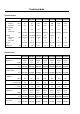
Technical data 7 Technical data W465H W475H W4105H W4130H W4180H W4240H W4300H 65 520 75 520 105 595 130 650 180 725 240 795 300 795 49 49 49 49 44 42 42 1100 1100 1025 980 930 890 820 5.4/7.5 x x 5.4/7.5 x x 7.
Technical data 8 Technical data W475N/M Innerdrum volume diameter litres mm Drum speed wash extraction rpm W485N/M W4105N/M W4130N/M W4180N/M W4250N/M W4330N/M 75 520 85 520 105 595 130 595 180 650 250 725 330 795 49 49 49 49 44 44 42 528/694 528/694 494/649 494/649 471/619 446/587 427/561 3.0/ 7.5/10 x x 4.8/9.3 13 x x 18 x x 23 x x 2.0/3.0/ 2.0/3.0/5.6 3.0/6.5/ Heating 7.5/10 electricity kW 5.4/5.6/7.5 5.4/7.
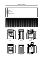
Technical data 1 2 3 4 5 6 7 8 9 10 9 Electrical connection Cold water Hot water Hard water Steam connection Drain Liquid detergent supply Control panel Soap box Door opening, W465H, W475H: ø 310, W4105H: ø 365, W4130H: ø 395, W4180H, W4240H, W4300H: ø 435 A W465H B 720 C D 690 1115 355 E F G H 720 825 45 I K L 1030 220 1010 135 M N O P R S 910 830 360 100 240 – W475H 720 690 1115 355 720 825 45 1030 220 1010 135 910 830 360 100 240 – W4105H 830 705 1300 365 7
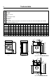
Technical data 10 1 2 3 4 5 6 7 8 9 10 Electrical connection Cold water Hot water Steam connection Drain Liquid detergent supply Control panel Soap box Water reuse Door opening, W475N/M, W485N/M: ø310, W4105N, W4130M: ø365, W4130N, W4180M: ø395, W4180N, W4250N/M, W4330N/M: ø435 A B C D E F G H I K L M N O P R 725 825 45 1030 215 1010 130 830 385 - 100 210 W475N/M 660 W485N/M 660 730 1115 355 765 825 45 1030 215 1010 130 830 385 - 100 210 W4105N/M 720 70
Technical data 11 W465H W475H W4105H W4130H W4180H W4240H W4300H 18.3 18.3 17.1 16.3 15.5 14.8 13.7 3.1 ± 0.5 4.2 ± 1.0 5.2 ± 1.0 6.2 ± 1.2 Frequency of the dynamic force Hz Max floor load at extraction kN 1.8 ± 0.5 1.9 ± 0.5 2.5 ± 0.5 W475N/M W485N/M W4105N/M W4130N/M W4180N/M W4250N/M W4330N/M Frequency of the dynamic force Hz 9.3 9.3/11.6 8.7/10.8 8.7/10.8 8.3/10.3 Max floor load at extraction 1.6 ± 2.8/ 1.7 ± 3.1/ 2.1 ± 3.6/ kN 1.2 ± 2.6 1.7 ± 3.3 2.1 ± 4.0 2.3 ± 4.1/ 2.
Machine presentation Machine presentation 13 1 Description General 1 The machines covered in this service manual include the following models: Drum volume Model name (litres) 65 W465H 75 W475H/M/N 85 W485M/N 105 W4105H/M/N 130 W4130H/M/N 180 W4180H/M/N 240 W4240H 250 W4250M/N 300 W4300H 330 W4330M/N The machines feature an electronic programme unit with fixed washing programmes that may be changed using optional accessories.
Machine presentation 14 Function General 2 This section presents a general overview of the functions of the machine. Most functions are then presented in detailed in separate chapters later on in this service manual. The machine is freely suspended, which means the outer drum and motor are mounted on a supporting ”cradle” that rests on four shock absorbers for dampening the imbalance in the machine. The washer drum (inner drum) is belt driven by a motor.
Machine presentation 15 2 1 2 3 4 5 18 17 16 6 15 7 14 13 8 12 9 11 10 1. Detergent drawer 10. Shock absorber (not M- and N-model) 2. Water inlet valves 11. Avloppsventil 3, Power supply 12. Support 4. I/O-board 13. Door 5. Rear electrical module 14. Door lock 6. Motor control 15. Program knob 7. Outer drum 16. Display 8. Coil spring (not M- and N-model) 17. Control panel 9. Motor 18.
Machine presentation 16 Program unit 3 3 The control panel contains a program knob and a display. The panel can also be equipped with two preset buttons. Program unit The control panel and display are used by: • the user to select the machine’s fixed wash programs, to select up to two options for each wash program and for information on the wash process and any fault indicators. • service personnel for navigation and control of the program unit’s service program.
Machine presentation Motor and motor control 5 6 5 17 1 The washer drum (inner drum) is belt driven by a frequency controlled motor. The motor is located on a motor shelf under the outer drum and has been arranged with a belt tensioner. Motor control is microprocessor controlled and can control the acceleration of the drum, its rpm and its retardation very precisely. Motor control communicates with the program unit through a serial interface.
Machine presentation 18 Door lock 7 8 The door lock is electromechanical with twin safety breakers. The lock is bi-stable, i.e. the lock must be given an active signal from the program unit to lock as well as unlock the door. 7 1 A separate circuit integrated in the program unit checks and controls the locking and unlocking of the door through a lock module. The circuit has separate controls that the drum is empty and that it is stationary.
Machine presentation Heating 9 19 9 1 Electric heating heats the washing water with three elements accessible from the front of the machine. The machine’s heating system is described more thoroughly in the section Heating. Water connections 9 The machine can have one, two, three or four water inlet valves depending on the machine size and customer requirements. In this unit there are also eight connections for an external detergent feeder.
Machine presentation 20 Detergent compartment 11 11 The detergent compartment has four compartments for prewash, main wash, rinse and bleaching agent/liquid detergent. 1 The machine’s detergent compartment is described more thoroughly in the section Detergent compartment. Drain valve 11 The valve is a diaphragm valve that is opened and closed through water pressure. The control valve is mounted by the water valves. The machine’s drain valve is described more thoroughly in the section Drain valve.
Troubleshooting Troubleshooting This programming manual is intended for personnel with the authority to adjust parameters in the machine’s existing wash programs, programming slot meters, reading statistics and configuring certain machine interfaces with the user. Programming is achieved using menus in the display while the machine is in service mode. General information on troubleshooting The troubleshooting section is used to trace faults in the machine to a defective component or unit.
Troubleshooting 22 Faults with fault code A fault in the program or in the machine is indicated on the display by an error message comprising an error code and a descriptive text. 1 1 Fault code FAULT 001 NO WATER 6204 Fault code The following is a brief description of all fault codes. The following pages describe fault codes, possible causes and corrective measures for each code.
Troubleshooting Fault code Text message 012 Program failure 013 No motor comm. 014 Level adjust. 015 Emergency stop 017 Door lock 018 Start not allowed 019 Master comm. 020 I/O MCU Interlock 021 I/O Communication 022 Oil 023 No I/O addressed 024 Checksum from DLCU 027 Level offset 028 CPU/DLCU low level 031 Heat sink too hot 032 Motor too hot 033 No interlock 035 Motor short circuit 036 Interlock hardware 037 Low DC voltage 038 High DC voltage 043 Unb.
Troubleshooting ���� ����� ���� ���� ����� ����� ����� ������ ����� ����� Alt. 1 ����� Service mode is engaged by using one of the following alternative: 2 ����� Engaging servicemode ���� 24 Alt. 1 Service switch on the CPU board under the top cover on the front of the machine. Alt. 2 Service switch on the I/O board at the rear of the machine to the right of the electrical connection. Alt.
Troubleshooting Description of fault codes and causes Fault code 01, NO WATER This fault code is generated by the programming CPU card. When filling with water, the level specified by the wash program must be attained within a certain time. This time is normally set to 10 minutes but can vary depending on the type of machine and the software. If the filling time eceeds the maximum allowed filling time, fault code 01 will be displayed.
Troubleshooting 26 Fault code 04, NTC LOW TEMP This fault code is generated by the programming CPU card. This fault code is displayed if the temperature around the NTC sensor is below approx. -9 degrees C. A low temperature means the resistance in the sensor is too high, above approx. 23.7 kohm. This can be because the machine has been standing outdoors, an open circuit in the sensor, a break in the cable to the sensor, etc.
Troubleshooting Fault code 07, DRUM OVERFILLED This fault code is generated by the programming CPU board. The fault code arises if the drum has been filled with water above a predetermined level during an on-going wash program. It can be caused by a blocked level hose, drops of water in the level tube, defective filler valve, defective electronic filler control, etc. Action: • Blow through the level hose and check that it is not blocked and does not contain any water.
Troubleshooting 28 Fault code 09, KLIXON This fault code is generated by the programming CPU board. The fault code means that the temperature in the motor has been so high that the klixon breaker in the motor has been triggered. It can be caused by overloading the motor due to an overloaded drum, low rpm for long periods, defective klixon breaker in motor, short in cable between motor and CPU board, etc.
Troubleshooting Fault code 11, UNB. ON AT PROG. START This fault code is generated by the programming CPU board. The fault code means that the mechanical imbalance breaker is already active when the wash program starts. It can be caused by a defective imbalance breaker, mechanical problem making the imbalance breaker always active, short in the edge connection or cables, etc. Fault code 12, PROGRAM FAILURE This fault code is generated by the programming CPU board.
Troubleshooting 30 Fault code 15, EMERGENCY STOP This fault code is generated by the programming CPU board. The fault code arises if the emergency stop switch has been activated on the machine. The cause can be inadvertent activation of the emergency stop, defective emergency stop switch, incorrect or shorted cable, etc. Fault code 17, DOOR LOCK This fault code is generated by the programming CPU card. The fault code arises if the door lock is locked at the start of the wash program, i.e.
Troubleshooting Fault code 20, I/O MCU INTERLOCK This fault code is generated by the programming CPU board. The program controller has read from the motor control or I/O board that the interlock is not active. The reason for interlock failure can be a problem with the hatch lock, damaged motor supply cables or the I/O board with interlock voltage etc. The most probable fault source is the I/O board. Fault code 21, I/O COMMUNICATION This fault code is generated by the programming CPU board.
Troubleshooting 32 Fault code 23, NO I/O ADDRESSED The fault code means that there is no I/O board addressed in the system at all. Action: • (Requires password) Readdress the existing I/O board from the service menu. Fault code 24, CHECKSUM FROM DLCU This fault code is generated by the programming CPU board. The program unit has detected a fault in the internal communication in the DLCU-processor. Action: • Replace the CPU board.
Troubleshooting Fault code 28, CPU/DLCU LOW LEVELS The DLCU contains a mechanical level monitor which ensures that there is no water in the machine when the lock opens. To ensure that the level monitor functions correctly, the mechanical level monitor is compared with a nominal value generated by the CPU, which is compared with the electronic level check.
Troubleshooting 34 Fault code 32, MOTOR TOO HOT This fault code is generated by the motor control. Each time the motor is started from stationary, the motor control will first measure the resistance between two phases in the motor. The motor control processor governs the output transistors so that a determined DC current flows between two phases in the motor winding.
Troubleshooting Fault code 33, NO INTERLOCK This fault code is generated by the motor control. The motor control must be powered with 230V/50 Hz on the interlock input in order to drive the motor. This signal is confirmation that the door is closed and locked. Motor control receives its commands to rotate the drum from the timer via a serial communication link between the motor control and timer.
Troubleshooting 36 Fault code 35, MOTOR SHORT CIRCUIT This fault code is generated by the motor control. The motor control reads the power consumption of the motor continuously. If the current for some reason gets too high (= exceeds a certain limit), the motor control will cut the current to the motor. After the motor has stopped (= tachometer indicates stationary motor), the motor control will attempt to restart it.
Troubleshooting Fault code 36, INTERLOCK HARDWARE This fault code is generated by the motor control. The motor control must be powered with 230V/50 Hz on the interlock input in order to drive the motor. The interlock circuits in the motor control have been split into two channels so that a component fault in motor control cannot give a false confirmation that the door is locked. These two channels are checked against each other.
Troubleshooting 38 Fault code 38, HIGH DC VOLTAGE This fault code is generated by the motor control unit. The motor control unit constantly measures the voltage over the mains input. If the voltage is too high (= exceeds a certain limit), the motor control unit will shut off the current to the motor. Once the motor has stopped (= the tacho sensor indicates that the motor is stationary), the motor control unit checks to see whether the input voltage is still high.
Troubleshooting Fault code 45, MOTOR NOT FOLLOW This fault code is generated by the motor control. The motor control must always receive information on the rotation of the motor from the tacho sensor in order to rotate. If the tacho sensor is not working, the motor can rotate for max. 10 seconds during the starting process. After this period, the ”MOTOR NOT FOLLOWING” fault code will be activated.
Troubleshooting 40 Fault code 52, CHARGE CIRCUIT DLCU contains an arming circuit that is charged when the door lock coil is to be activated. For safety reasons, this arming circuit must be discharged when the door lock coil is not to be activated. If the arming circuit for operating the door lock is charged when it is not supposed to be, a fault message will be sent to the CPU processor. If the fault ceases, the message will not be sent to the CPU.
Troubleshooting Fault code 54, TACHO, NO SET SIGNAL DLCU counts the tacho pulses from the motor in order to guarantee that the drum is stationary when the door is opened. To ensure that the signal from the tacho generator is working correctly, DLCU compares the tacho signal to a default value from the CPU processor, which is due to the CPU having activated the motor.
Troubleshooting 42 Fault code 56, SET SPEED DOOR OPEN DLCU counts the tacho pulses from the motor in order to guarantee that the drum is stationary when the door is opened. To ensure that the signal from the tacho generator is working correctly, DLCU compares the tacho signal to a default value from the CPU processor, which is due to the CPU having activated the motor. If the default value is on when the door lock is unlocked, a fault message will be sent to CPU.
Troubleshooting Fault code 60, ACTUATOR CIRCUIT The DLCU processor controls the door lock actuator coil. The DLCU processor checks continuously that the coil is engaged. DLCU can detect a break in the circuit (>50 kohm) (DLCU cannot detect a short in the circuit). If there is a break in the actuator circuit, CPU will be notified; the fault message will disappear if the fault ceases.
Program unit Program unit 45 1 Description General Information The program unit is electronic and comprises a circuit board containing microprocessor, program memory, current regulating circuits, temperature and level control, etc. 1 The program unit receives its power from a separate voltage unit. 2 The program unit receives information from the temperature sensor, door lock and level switches. There is also a serial interface to the motor control.
Program unit 46 Inputs and outputs The program unit board has the following inputs and outputs: 3 Board connector Function Con 1 Input from temperature sensor (Temp) Con 2 Databus (D-bus) Con 3 Databus (D-bus) Con 4 Tacho Con 5 Communication, motor control unit (M-com) Con 6 Connection for software/service download (P-load) Con 7 Input, Level sensors (level) Con 8 Serial communication (RS 232) Con 9 Input, Emergency stop (EMERG) Con 10 Input, Free wash (key switch) (FREE W) Con 11
Program unit 47 Menu tree The machine software is constructed with menus that are structured according to the menu tree below. The menus become available when the machine is in service mode, see under the heading ”Engaging service mode”. SERVICE ACTIVATE OUTPUTS SHOW INPUTS ARTICLE NUMBER SHOW DLCU COM. RESET DLCU SHOW MCU COM. RESET MCU SHOW SINGLE SHOW COM.
Program unit ���� ����� ���� ���� ����� ����� ����� ������ ����� Alt. 1 ����� 4 ����� Service mode is engaged by using one of the following alternative: ����� Engaging servicemode ���� 48 Alt. 1 Service switch on the CPU board under the top cover on the front of the machine. Alt. 2 Service switch on the I/O board at the rear of the machine to the right of the electrical connection. Alt.
Program unit Service program 49 7 The service program is used to facilitate troubleshooting the machine. Using this program you can: MAIN MENU 01.00.00.00 SERVICE PARAMETER PROGR.
Program unit 50 ACTIVATE OUTPUTS 9 Select the ACTIVATE OUTPUTS row and press the knob. The display now shows the functions (outputs) that can be activated. • • • • • • • • • • • • • • • • • • • • • • • • • • • • • 10 DOOR NORMAL DRAIN DRAIN A-D COLD WATER HOT WATER HARD WATER TANK 1-4 WATER HEAT 1 HEAT 2 HEAT 3 POWDER DETERGENT LIQUID DETERGENT INTERLOCK MOTOR PROGRAM RUN MACHINE FREE DRUM CW DRUM CCW DISTRIBUTION LOW EXTRACT MEDIUM EXTRACT HIGH EXTRACT TURBO EXTRACT CLUTCH START CAP.
Program unit SHOW INPUTS 11 12 Select the SHOW INPUTS row and press the knob. The display now shows the sensor signals (inputs) that can be activated. • • • • • • • • • • • • • • • • • • • • • • • • • • • • • • • • • • • • • • • • • • • • • • • • • • • • • • • • COUNT 1 DOOR LOCK DOOR CLOSED START BUTTON CPU SERVICE BUTTON PRICE PROGRAMMING PRICE REDUCTION FREE WASH COIN 1 COIN 2 EMERGENCY STOP ALTER.
Program unit 52 ARTICLE NUMBER 13 14 Select the ARTICLE NUMBER row and press the knob. You can now choose on the display to show the article numbers for the program units, I/O boards, motor control or DLCU fitted in the machine. Select the unit for which to show the article number. SHOW DLCU Com. 15 16 Select the SHOW DLCU COM. row and press the knob. The display shows the status of the communication to and from the DLCU board. For detailed information, please contact your supplier.
Program unit SHOW MCU Com. 18 Select the SHOW MCU COM. row and press the knob. 19 The display shows the status of the communication to and from the frequency control. RESET MCU 20 Reset frequency control from the fault code by selecting the RESET MCU row and pressing the knob. The reset will take a few seconds. The square which lights up to the right of the menu bar indicates that there is a fault code in the DLCU (Door lock control unit). SHOW singLE Select the SHOW SINGLE row and press the knob.
Program unit 54 WEIGHT CALIBRATION 21 Select the WEIGHT CALIBRATION row and press the knob. • Operate the machine with an empty drum. • After weight calibration, the weight deviation will be shown in a hexadecimal format on the bottom line of the display. • The drum will go faster and slower a number of times during weight calibration. This is normal. Weight calibration will take a few minutes.
Program unit MEASURE UNBALANCE 25 26 Select the MEASURE UNBALANCE row and press the knob. Put in a known unbalance weight. A corresponding weight must be shown in the display once imbalance measurement has taken place. 55 25 *SERVICE* 01.12.00.00 MEASURE WEIGHT MEASURE UNBALANCE DISPLAY TEST EXIT Confirm that measurement is to be performed with YES or return to the previous menu with NO. This function is used to check that the machine is measuring unbalance correctly.
Program unit 56 Config 1 29 The configuration 1 menu contains all the functions and parameters that service personnel can change without a password. Engage the machine’s service mode. 29 Select the CONFIG 1 row in the main menu and press the knob. All the available parameters will now be displayed. The table below gives the default value on the right. • • • • • • • • • • • • • • • • • • • • • • • • • • • • • • • • • • PAUSE PERMITTED RAPID ADVANCE REGRET TIME NEW PROG.
Program unit • • • • • • • • • • • • • • • • • • • • • • • • • • • • • • • 30 31 32 TIMEOUT,PAUSE buzz. sec MAX FiLL TIme, sec 6. water in drum 7. drum overfilled 10. drum not drained MAchINe AdDRESS PASSword show weight time, sec MAXDIFf.wash time min DEFAULT heat back light time SEc. OFFS.level reading MM display warning, sec flush delay, liq. sec flush on, liq. sec flush delay, powd.sec flush on, powd.sec level cool down, scu coOl step temp coOl middle temp DISPLAY STATIST. SEC. SHOW STAT. DOUBLECLI.
Program unit 58 PAUSE PERMITTED Select whether it should be possible to pause during an on-going wash program. Yes = A pause is allowed during a wash program. No = A pause is not allowed during a wash program. RAPID ADVANCE Select whether is should be possible to step rapidly forward or backward through the wash program while it is in progress. Yes = It is allowed to step rapidly through a wash program. No =It is not allowed to step rapidly through a wash program.
Program unit SHOW TEMP Select whether the current water temperature is to be shown on the display window while a wash program is in progress. This function cannot be shown on the display at the same time as the SHOW IS LEVEL function, only one of the functions can be shown at one time. Yes = The water temperature is shown. No = No temperature is displayed in the display window. SHOW IS LEVEL Select whether the current water level is to be shown on the display window while a wash program is in progress.
Program unit 60 TEMP cONTRol water Select whether the machine is to control and adjust the water temperature by opening and closing the main valves for hot and cold water during filling. Yes = Control of main valves during filling. - Alt.1: Hot and cold water valves both open. If the set water temperature is exceeded, the hot water valve will be shut automatically. - Alt. 2: Only hot water valve open.
Program unit AUTO START paid Select whether the machine is to be able to start automatically, when full price has been paid, for the chosen wash program. Yes = Automatic start engaged. Note! If the signal for blocking the start button is engaged, it also applies to the blocking signal for the automatic starting function. No = The automatic start function is disengaged.
Program unit 62 show prog. counter Select whether the contents of the machine’s counter of completed wash programs should be shown in the display window while a wash program is in progress or outside the wash program without going into service mode. The counter is shown on the display after pressing the control knob twice in quick succession. Yes = The contents of the program counter can be displayed if a time has been set for the function SHOW.STAT.DOUBLECLI.
Program unit AUTO PROG SELECT Choose whether wash programme 1 should be selected automatically and displayed in start position as soon as the door is opened/closed or coins are inserted in the coin slot. Yes = Automatic programme selection takes place. No = Automatic programme selection off MEASURE weight Select whether the count weight function should be activated. Note that the function cannot be activated for wash programs that are programmed for no weight count. Yes = Count weight activated.
Program unit 64 coin value 1 and 2 Specify with the knob the value (0 999) for the respective coin slot. For example: Coin 1, 1 = 1 EURO Coin 2, 5 = 5 EURO Coin 1, 50 = 50 Cent Coin 2, 100 = 1 EURO Setting the price to 300 and selecting COLON WHEN PRICE will display the price as 3:00. DOT when PRIce On machines with coin counter, the price can be displayed with or without dot (0:00 or 000). Yes = The dot is displayed. No = The dot is not displayed.
Program unit MAchINe AdDRESS Specify with the knob the machine’s address (0 - 127) that is used when the machine is connected to the CMIS system. PASSword Select whether the functions under CONFIG 1 should be password protected or not. The password comprises four numerals. The code 0000 means no password is required for the CONFIG 1 menu. The password code can be changed or removed at any time. show weight time, sec Used for machines with weight count.
Program unit 66 OFFS.level reading MM The value set is subtracted from the ACTUAL value in mm in order to compensate for the distance between the level recess and the bottom of the inner drum. Once this has been set, the water level above the bottom of the inner drum, etc. can be read. display warning, sec Specify with the knob the number of seconds the warnings are to be displayed. Warnings are e.g. empty tank alarm from detergent that is shown each time a wash program is displayed.
Program unit flush on, powd.sec Rinse times for rinsing detergent after the drum has been filled with water. The time is given in steps of 1 second in the range 0 -255 seconds. level cool down, scu Select the level to which the machine should be filled with the cold water valve if the wash program includes the rapid cooling function. The level is given in divisions (DIV) in the range 0 - 850. cool step temp Specify the maximum drop in temperature allowed per minute during cooling.
Program unit 68 Activate wash progr. The ACTIVATE WASH PROGR. menu is used to specify the wash programs in the program library that are to be made available to the user and in which order the wash programs are to be presented in the display. 34 35 Engage service mode and select the ACTIVATE WASH PROGR. row in the main menu. Press in the knob. All the wash programs contained in the installed program library are now shown. 34 MAIN MENU 08.00.00.00 RESET TO FACTORY ACTIVATE WASH PROGR.
Program unit Unbalance detection When the drum in a drain sequence starts its acceleration from wash rpm to distribution rpm, the extreme unbalance measurement will start once about 90% of the distribution rpm has been attained. Subsequently, during the entire remaining super unbalance measurement, the distribution time and during the entire subsequent extraction time, the program unit will detect whether there is any extreme unbalance. In case of extreme unbalance that can arise if e.g.
I/O modules 71 I/O modules General Washing machines may be equipped with either one or two I/O modules: • I/O module 1 controls internal machine functions and is always installed in the machine prior to delivery. It controls outputs to water valves, waste discharge and heating. • I/O module 2 is installed as an optional extra, controlling the external functions of the machine, i.e. inputs from payment and booking systems and outputs to detergent pumps.
I/O modules Function options via the service program 1 Engage service mode, highlight the SERVICE line in the main menu and press the knob. 1 MAIN MENU 01.00.00.00 SERVICE PARAMETER PROGR. STATISTICS CONFIG 1 CONFIG 2 ADJUST DISPLAY The display will now show the different submenus in the service program. 2 3 4 Highlight the ARTICLE NUMBER line and press the knob. You can now choose to view the article numbers of program devices, I/O modules, motor control or DLCUs installed in the machine.
I/O modules Function options via program designation 5 The parameter software installed in a machine’s program device on delivery is specified on 2 plates, one located on the inside of the door and one by the machine's electrical connection.
I/O modules 74 Function options for Type 1 and Type 2 I/O modules Function options, I/O module Type 1 A B C D E Waste Waste Waste Waste Waste Heating Heating Heating Heating Heating 3 Hot water 3 Hot water – 1 Hot water 1 Hot water 3 Cold water 4 Cold water 4 Cold water 5 Cold water 1 Cold water Function options, I/O module Type 2 A B C D E F G External slot meter Start block Start block Price reduction PC 5 Start block Heat switch Price programming Start/Pause
I/O modules Replacement of I/O module I/O modules 1 and 2 are installed in the same way, but are located in different parts of the machine. The following illustration only shows how to replace I/O module 2, but the same procedure also applies to I/O module 1. 75 8 � � � � � � � � � �� �� �� �� �� �� �� I/O module 2 is located on the rear PCB and accessible once the protective plate is removed. 8 • Remove the electrical connections on the module.
I/O modules 76 External connections to I/O module type 2 12 1=N 2=L 4 = Earth Connection of external dosing equipment 1 2 3 4 The external dosing equipment power supply must never be connected to the machine's incoming terminal block. 2 1 3 6 Machines fitted with connectors 12 9 5 • Connect the pump assembly to connections A and B on the washing machine. Connect the signal cable to B and the power supply to A.
I/O modules 77 Outputs 14 15 14 • External power supply (e.g. 24V DC) for pumps is to be connected to 9 and 10. If the internal power supply (from the washing machine) is to be used, it may be taken from 1 (N) and connected to 9 and from 2 (L) and connected to 10. The outputs may be loaded with max 0.5 A.
I/O modules 78 16 • Connection 8 may be connected if there is to be a pause in the wash program, e.g. while detergent is being dosed. The figure shows an example of engaging a 24V pause signal. The wash program will pause for as long as the pause signal remains active (high). 16 Dosing system 0V 24 V 3 Com 5-24V Pause signa 24V DC 8 6266 17 • If connection 7 is connected, an error message will be shown in the display if any of the chemical tanks are empty.
I/O modules 79 Circuit diagram of function options for I/O module type 2 The wiring diagram for I/O module type 2 may be one of the following variants: 22A, 22B, 22C, 22D, 22E, 22F or 22G.
I/O modules 80 22B � � � � ����� ����� ����� ����� ����� � �� �� �� �� �� �� �� � � �� �� �� ��������� ��������� ��������������� ����� � ������ ��������� �������������� � � � � ���� � � ������� ������� � ��������� � ����������������� � ��� ����� � ����� ����� � �������������� ������������� ��������� ����� ���������� ��������������� �������� ���������� ������������� �������� ��������� ��� �������� ���������� �������� � �������� � �������� �
I/O modules 81 22C � � � � � �� �� �� �� �� �� �� �� ����� �� ����� �� � ������ ������������ � � � � ����� ����� ����� ����� � ��������������� ����� �������������� ����� �������� � ������� �������������� ��������������� �������� ����� � ������� � ������������ � �������������� � ����������������� �������������� � ������������� � �������������� ����� � ����� � ���������� �������� � �������� �������� �������� � � ���� ������ � ������ � ������
I/O modules 82 22D � � � � �� ����� ����� ����� ����� ����� � ������� � � � � �� �� �� ������ �� �� �� �� �� �� ����� � �������������� � � ������� ��������� � � � � ���������� ����� �������� �������� ���������������������� � ����������������� ���������� � ������������� � ����� � �������� � �������� �������� � � ���� ������ � ������ � ����� � ����� � ����� � ������� � ������� ������ � ����� ������� � ������� ������� ����� ����������
I/O modules 83 22E � � � � � �� ����� ����� ����� ����� ����� � � � � � � � �� �� �� ������ �� �� �� �� �� �� ����� � � ������� ������� � ��������� � �������������� � ������������� � ����������������� � ����� � ���������� � �������� �������� � � ���� ����� � ����� � ����� � ����� � ����� � ������� � ������� ������ � ����� ������� � ������� ������� ����� ���������������� ������� �������������� 6315 • Heating pause: By connecting a signa
I/O modules 84 22F x
� � � � � � � � � �� �� �� �� �� �� ����� � � �� � �� ������������� ����� � ���������������� ������� �������������� � �� � • The gas heating unit must be connected to connections 17, 18 and 19.
I/O modules 86 ����������������������� ���������������� ���������������� Machines with I/O module type 3 � � � ����� � � � � ����� � ���� ����� ��� � � ����� � ��� ���� � � � � 6636 • By maintaining an active (high) signal on connection 3 "Price reduction”, the price of the wash program can be reduced. This function has a number of uses, including providing reductions during a specific period of the day.
I/O modules Addressing I/O modules After replacing an I/O module or in instances where a second module has been added to a washing machine, the new I/O module must be addressed in order to activate its function options. The function options of the module are controlled by the parameter software loaded on the relevant program device. 87 18 MAIN MENU 08.00.00.00 RESET TO FACTORY ACTIVATE WASH PROGR. QUICK START BUTTONS I/O ADDRESS PRICE PROGRAMMING EXIT • Engage the machine's service mode.
Door and door lock Door and door lock Description 89 1 1 General 1 The door locks consists of the following: • Door lock, which contains - An actuator that locks the door lock and also has two built-in micro switches, S4a and S4b. The actuator is bi-stable, i.e., it has two stable positions: locked door and unlocked door. The actuator must receive a pulse to lock and unlock the door lock. S4a and S4b are both closed when the door is locked. - A micro switch S3 that is closed when the door is closed.
Door and door lock 90 Function The door lock locks the door When the door is closed (closed door lock switch S3), the programme unit may request door locking by applying a voltage of 200-240 V on the door lock controller A31 input X92. 2 The following check is made by the A31 card prior to locking of the door: • No water in drum - input "level" from level guard B2 is closed = 0 V • Drum not turning - pulse frequency on input "Tacho" from rotation sensor B3 less than 0.4 Hz.
Door and door lock 91 The door lock unlocks the door The programme unit requests door unlocking by applying 0 V on input X92 of the door lock controller. 3 The following check is made prior to unlocking of the door: • No water in drum - input "Level" from level guard B2 is closed = 0 V • Drum not turning - pulse frequency on input "Tacho" from rotation sensor B3 is less than 0.4 Hz.
Door and door lock 92 Repairs 4 Repair work on the machine should only be done by specially trained personnel. Emergency opening of door lock 4 1. Take down power from the machine by turning the main power switch to the 0 position. 2. Remove the front cover or top cover. When replacing the door lock, it is recommended to remove the front cover. 3. Press down the emergency opening button.
Door and door lock Replacing the door lock 1. Take down power from the machine by turning the main power switch to the 0 position. 2. Remove the front cover alt. side pole. 3. Remove the door (two screws in each hinge). 4. Remove the front panel. 5. Remove the door lock (three holding screws). 6. Verify the strap positions on the cable for the lock. Cut the necessary straps to undo the cables leading to the lock. 7. Undo the connectors. 8. Replace the door lock. 9. Reconnect the new (door) lock. 10.
Motor and motor control Motor and motor control Warnings DANGER Be careful when measuring the electric components in the motor control. All components have a potential difference of approx. 300 V in relation to protective earth and neutral. When the green LED on the motor control card is lit, the components carry dangerous voltages. The motor control lose all voltage about 10-30 seconds after the voltage has been disconnected and the motor has stopped.
Motor and motor control 96 Description 1 Motor 1 The motor is fitted in a bridge carrier under the outer drum. It drives the washing drum using a drive belt. The motor is frequency-regulated and is controlled by a microcomputer control. The various speeds for normal operation, distribution speeds and extraction as well as acceleration/ retardation can be controlled with a high degree of precision.
Motor and motor control Motor control 2 97 2 The motor control unit is microcomputer controlled and is situated under the top cover of the machine, right above the outer drum. Motor control U1 The unit consists of a PCB (mother board) fitted on a heat sink that does double-duty as part of the housing. The cable harness is directly connected to the PCB, voltage supply input and the voltage supply to the motor using connectors; the other cables are connected with flat connectors to the PCB.
Motor and motor control 98 Function DANGER Be careful when measuring the electric components in the motor control. All components have a potential difference of approx. 300 V in relation to protective earth and neutral. When the green LED on the motor control card is lit, the components carry dangerous voltages. The motor control lose all voltage about 10-30 seconds after the voltage has been disconnected and the motor has stopped.
Motor and motor control The motor control is also able to deliver the various instantaneous and output values during constant speed, acceleration and retardation. These values are used to calculate the weight of the loaded laundry and to detect any load imbalances. A separate imbalance switch can also be connected to the motor control. The safety system of the machine includes double detection of the door lock. Both the programme unit and motor control use different switches to detect proper door locking.
Motor and motor control 100 X311: Voltage supply 6 Input voltage, single phase or rectified three-phase 6 min: 200V-15% max: 240V+10% X312: AC supply to motor and input from the motor thermal protector The motor is fed with alternating current with varying frequency that is proportional to the motor speed. W465-W4130H Card No. X 312:1 X 312:2 X 312:3 Function AC supply to motor, phase 1 AC supply to motor, phase 2 AC supply to motor, phase 3 W4180-W4240H Card No.
Motor and motor control LED indications 101 7 7 Two LEDs, one yellow and one green, indicate any errors on the motor controller and motor. 8 The table below shows the blinking patterns of the various error codes. Green LED Yellow LED 6657 8 Green LED LED blinking pattern Cause OK blink (brief pause every 5 seconds) Microcomputor in motor control unit not working, voltage is on. approx. 5 seconds Current limiter of motor control has switched on.
Motor and motor control 102 Repairs 9 Mounting bolt Repair work on the machine should only be done by specially trained personnel. Spacer Motor replacement Disassembly 1. Take down power from the machine. 2. Remove the rear cover. 3. Undo the bracket for the drain hose connector from the lower rear piece, then remove the rear cover. Motor cable 4. Undo the ground connection from the motor. 9 5. Remove the drive belt by pulling the belt towards you while rotating the drum by hand.
Motor and motor control 3. Connect the new motor to the cable and use straps to secure the cable. 103 10 4. Connect the motor cable to the motor. 5. Fit the lower rear piece and secure the drain hose connection with screws. 6. Fit the upper rear piece. 7. Connect the voltage supply and verify that the motor operates normally. B, C Adjustments A Drive belt tension The drive belt is pre-tensioned upon delivery from the factory.
Motor and motor control 104 From machine No. 520/111628-111640 520/115134-115143 520/120399-120408 520/12102112 13 12 To adjust drive belt tension: first undo the motor retaining screw (A) by using two cap keys. When undoing screw (A) use one cap key as holder-on on the screw's nut. Press down the motor by using a screw driver in order to tension the belt. Tighten the retaining screw and check the tension according to table.
Drain valve Drain valve 105 1 H – model Description 1 The drain valve is situated on a flange at the bottom of the outer drum and can be accessed from the front after removing the front cover. The drain valve consists of the following principal parts: • Lower part with rubber diaphragm. • Piston and cylinder. • Pressure plate and recoil springs. Drain valve 6562 • Rubber diaphragm with drain connection. • Upper part with connection for outer drum.
Drain valve 106 Function 2 The drain valve uses the water pressure in the cold-water inlet to close the valve. A feed hose is connected between the water inlet and the control valve. When the control valve operates (drain valve should be closed), the control valve opens the water pressure onto the feed hose, which is connected to the lower part of the drain valve. When the lower part is filled with water, the lower part diaphragm pushes up the piston.
Drain valve Repairs 107 3 1 Repair work on the machine should only be done by specially trained personnel. 2 3 Disassembly 4 5 6 For repair works on the drain valve, there is a risk that water still left in the machine may flood onto the floor. Be sure to dry up any spilled water since it may cause people to slip and hurt themselves. 7 8 9 101772 1. Take down power from the machine. 2. Remove the front cover. 3 3. Disconnect the drain hose from upper part of the valve. 4.
Drain valve 108 Assembling 5 6 5 1. Connect the pressure hose to the lower part of the valve. Verify that the hose is not bent or pinched. 1 2. Fit the rubber bellows onto the sleeve coupling. 2 3. Hook the valve onto the bolts and turn the valve into position. Secure the 4 retaining bolts of the valve. 3 4 4. Secure the hose clamp at the connection of the rubber bellows on the sleeve coupling. 5 5. Connect the drain hose to the upper part of the valve. 6 6.
Detergent compartment Detergent compartment 1 Description Detergent compartment The detergent compartment of the machine is designed for use with powder and liquid detergent. The compartment is divided into four subcompartments as follows: 1 109 • Compartment 1 - For pre wash with powder or liquid detergent. 2 • Compartment 2 - For main wash with detergent powder. • Compartment 3 - Rinse. • Compartment 4 - Main wash with liquid detergent or, bleaching-agent.
Heating Heating 111 1 Description Contactor Electric heating 1 The heating system of the machine consists of: • Three heating elements for heating the water in the drum. • A temperature sensor to detect the water temperature in the drum. • One or two heating contactors for switch-on/ switch-off of the heating elements. The heating elements and the temperature sensor are situated at the bottom of the outer drum close to the edge. They can be accessed front the front after the front plate is removed.
Heating 112 Function 2 Electric heating with fusible cut-out on element 2 2 1 The three heating elements in the machine are connected to separate phases and are switched on and off using one or two heating contactorrs, K21 och K22 (two contactors are used for higher heating power). The heating contactors are controlled by the programme unit A1, output (X36:7).
Heating Function (machines built for mop washing) 113 3 Electric heating without fusible cut-out on element 3 1 The three heating elements in the machine are connected to separate phases and switched on and off using two serial heating contactors. Heating contactor K21 is controlled by programme unit A1, output (x36:7). Heating contactor K22 is regulated by a standalone mechanical level control.
Heating 114 Repairs Repair work on the machine should only be done by specially trained personnel. 5 Heating element Replacing the heating elements Wen replacing the heating elements, there is a risk that water still left in the machine may flood onto the floor. Be sure to dry up any spilled water since it may cause people to slip and hurt themselves. 1. Take down power from the machine. 2. Remove the front cover. 3. Make a note of how the heating elements are connected. 5 4.
Payment systems 115 Payment systems Various systems for payment and booking systems are available. See below table. Abbreviation Explanation CMS Coin Meter Single. Supplied with coin meter, single slot. CMD Coin Meter Double. Supplied with coin meter, double slot. CMSL Coin Meter Single Latch. Supplied with coin meter, single slot. With latch for coin interlock. CMB Coin Meter with strong box housing, no coin box. CMDSL Coin Meter Double Single Latch.
Payment systems 116 Abbreviation Explanation EBSK Electrolux BokningsSystem Kommunicerande. Supplied with interface for central booking/payment system EBSK. PCPXS Prepared Central Payment eXternal Start. Prepared for central payment system with external start, e.g. for the French market. PCB Prepared Central Booking. Prepared for central booking/payment system, i.e., Coges, Camping. EBS Electrolux Booking System. Prepared for central booking/payment system EBS, also for i.e. Aptus, In-time.
Abbreviations Abbreviations Abbreviation Explanation DLCU Door lock control unit MCU Motor control unit RMC Residual moisture control MIS Management information system CBT Central payment system SCU Scale unit SW Software DMIS Detergent management system EMIS External management information system CW Clock-wise CCW Counter clock-wise A/D SCU Analog/digital scale unit 117
Preventive maintenance Preventive maintenance To maintain correct and proper functioning and to prevent interruption of service, the following maintenance scheme should be adhered to. The maintenance interval should be adapted to how frequently the machine is used. Daily • Check the door and door lock: - Let the door remain open and try starting the machine. The machine should not start. - Close the door, start the machine and try opening the door.
Preventive maintenance - Verify that all internal hoses do not leak. - Inspect the drive belt. Adjust the tension or replace if necessary. - Check that water does not leak onto the floor. - If the heating time is unusually long, check the heating elements. If the water is very hard, check whether there are lime deposits on the heating elements. Decalcify the elements if necessary. Adapt the amount of deliming agent to the manufacturer’s guidelines.
www.electrolux.com/laundrysystems Share more of our thinking at www.electrolux.