EFC9140 WHGL9040CN EN DE FR IT Cooker Hood Dunstabzugshaube Hotte De Cuisine Cappa
DE FR EMPFEHLUNGEN UND HINWEISE 4 CONSEILS ET SUGGESTIONS 13 CHARAKTERISTIKEN 5 CARACTERISTIQUES TECHNIQUES 14 7 MONTAGE INSTALLATION 16 BEDIENUNG 10 UTILISATION 19 WARTUNG 11 ENTRETIEN ET NETTOYAGE 20 IT EN CONSIGLI E SUGGERIMENTI 22 RECOMMENDATIONS AND SUGGESTIONS 31 CARATTERISTICHE 23 CHARACTERISTICS 32 INSTALLAZIONE 25 INSTALLATION 34 USO 28 USE 37 MANUTENZIONE 29 MAINTENANCE 38
DE FR Willkommen bei Electrolux! Bienvenue dans le monde d’Electrolux Wir möchten uns bedanken, dass Sie sich für ein erstklassiges Produkt von Electrolux entschieden haben, welches Ihnen sicherlich viel Freude bereiten wird. Es ist unser Bestreben, eine breite Vielfalt von Qualitätsprodukten anzubieten, die helfen, Ihr Leben etwas komfortabler zu machen. Sie finden einige Beispiele auf der vorletzten Seite in diesem Heft.
www.electrolux.com EMPFEHLUNGEN UND HINWEISE MONTAGE • Der Hersteller haftet nicht für Schäden, die auf eine fehlerhafte und unsachgemäße Montage zurückzuführen sind. • Der minimale Sicherheitsabstand zwischen Kochmulde und Haube muss 650 mm betragen (einige Modelle können an einer geringeren Höhe installiert werden, beziehen Sie sich dazu auf den Absatz Raumbedarf und Installation). • Prüfen, ob die Netzspannung mit dem Wert auf dem im Haubeninneren angebrachten Schild übereinstimmt.
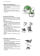
GERMAN 5 CHARAKTERISTIKEN Platzbedarf
www.electrolux.com Komponenten Pos. St. Produktkomponenten 1 1 Haubenkörper mit Schaltern, Beleuchtung, Gebläsegruppe, Filter 2 1 Teleskopkamin bestehend aus: 2.1 1 oberer Kaminteil 2.2 1 unterer Kaminteil 9 1 Reduzierflansch ø 150-120 mm 10 a 1 Flansch mit Ruckstauklappe ø 150 mm 10 b 1 Anschlussflansch ø 125 mm 14.1 2 Verlängerung Luftaustritt-Anschlussstück 15 1 Luftaustritt-Anschlussstück Pos. St. Montagekomponenten 7.2.
GERMAN 7 MONTAGE Bohren der Befestigungslöcher und Fixieren der Befestigungsbügel • Wie beschrieben einen Bezugspunkt 116 mm von der vertikalen Bezugslinie und 330 mm oberhalb der horizontalen Bezugslinie kennzeichnen. • Gleichermaßen an der gegenüberliegenden Seite vorgehen. • Mit einem Bohrer ø 8 mm die markierten Punkte bohren. • Die Dübel 11 in die Bohrungen einfügen. • Den unteren Bügel mit den mitgelieferten Schrauben 12a (4,2 x 44,4) fixieren. • Den oberen Bügel 7.2.
www.electrolux.com Montage des Haubenkörpers • Bevor der Haubenkörper eingehakt wird, die 2 Schrauben Vr bei den Haubenkörper-Anhakpunkten festziehen. • Den Haubenkörper bei den Schrauben 12a einhängen. • Die Halteschrauben 12a definitiv festziehen. • Den Haubenkörper mit Hilfe der Schrauben Vr ausrichten. Anschluss in Abluftversion Bei Abluftbetrieb kann die Haube vom Installateur wahlweise mittels Rohr oder Schlauch (ø150 oder 125mm) an die Außenrohrleitung angeschlossen werden.
GERMAN 9 Elektroanschluss • Bei Anschluss der Haube an das Stromnetz muss ein zweipoliger Schalter mit einem Öffnungsweg von mindestens 3 mm zwischengeschaltet werden. • Entfernen Sie die Fettfilter (s. Abschnitt „Wartung“) und versichern Sie sich, daß die Kabelverbindung in die Steckdose des Gebläses einwandfrei eingesteckt wird. Kaminmontage Oberer Kaminteil • Die beiden seitlichen Schenkel leicht auseinanderbiegen, hinter den Bügeln 7.2.1 einhängen und bis zum Anschlag wieder schließen.
www.electrolux.com BEDIENUNG Die Haube kann direkt auf die gewünschte Stufe eingeschaltet werden ohne daß man vorher auf die Gebläsetaste 0/1 drückt. Taste L Basisfunktion Zweifache Funktion Leuchtanzeigen Schaltet bei kurzem Drücken die Beleuchtung ein oder aus. Taste aus Durch 2 Sekunden langes Drücken der Taste wird die Beleuchtung im Modus “Notbeleuchtung” aktiviert. Die Lampen werden mit einer geringeren Taste leuchtet Leistung von zirka 5W gespeist.
GERMAN 11 WARTUNG Selbsttragender Metallfettfilter reinigung Rückstellen der Sättigungsanzeige • Den Gebläsemotor abschalten. • Die Taste F mindestens 4 Sekunden lang drücken, bis die Taste T1 als Bestätigung zu blinken beginnt. Filterreinigung • Sie müssen nach 2-monatigem Betrieb bzw. bei starkem Einsatz auch häufiger gereinigt werden, was im Geschirrspüler möglich ist. • Einen Filter nach dem anderen entfernen.
www.electrolux.com Austauschen der AktivkohleFilter Dieser Filter ist weder wasch- noch wiederverwendbar und ist auszutauschen, wenn die Taste F blinkt oder zumindest alle 4 Monate. Die Sättigungsanzeige erfolgt nur, wenn der Gebläsemotor eingeschaltet ist. Aktivierung / Deaktivierungder Sättigungsanzeige • Bei Hauben mit Umluftbetrieb erfolgt die Aktivierung der Sättigungsanzeige bei der Installation oder später. • Die Beleuchtung und den Gebläsemotor abschalten.
FRENCH 13 CONSEILS ET SUGGESTIONS INSTALLATION • Le fabricant décline toute responsabilité en cas de dommage dû à une installation non correcte ou non conforme aux règles de l’art. • La distance minimale de sécurité entre le plan de cuisson et la hotte doit être de 650 mm au moins (certains modèles peuvent être installés à une hauteur inférieure : se reporter aux paragraphes « Encombrement » et « Installation »).
www.electrolux.
FRENCH 15 Composants Réf. Q.té Composants de Produit 1 1 Corps de Hotte équipé de: Comandes, Eclairage, Groupe Ventilateur, Filtres 2 1 Cheminée Télescopique formée de : 2.1 1 Cheminée Supérieure 2.2 1 Cheminée Inférieure 9 1 Flasque de Réduction ø 150120 mm 10 a 1 Buse avec clapet 10 b 1 Anneau de raccord Ø 120 - 125 mm 14.1 2 Rallonge Raccord Sortie Air 15 1 Raccord Sortie Air Réf. Q.té Composants pour l ’installation 7.2.1 2 Brides Fixation Cheminée Supérieure 7.
www.electrolux.com INSTALLATION Perçage Paroi et Fixation Brides • Répéter cette opération sur le côté opposé. • Percer de ø 8 mm tous les points marqués. • Insérer les chevilles 11 dans les trous. • Fixer la bride inférieure 7.2.1 en utilisant les vis 12a (4,2 x 44,4) fournies. • Fixer l’équerre supérieure 7.2.1 (et, uniquement en cas d’installation de la hotte en version filtrante, fixer également le raccord 15) à l’aide des 2 vis 12a (4,2 x 44,4) fournies avec l’appareil.
FRENCH 17 Montage du Corps de la Hotte • Avant d’accrocher le corps de la hotte, serrer les deux vis Vr situées sur les points d’accrochage du corps de la hotte. • Accrocher le corps de la hotte aux vis 12a prévues à cet effet. • Serrer définitivement les vis 12a de support. • Agir sur les vis Vr pour niveler le corps de la hotte.
www.electrolux.com Branchement Electrique • Brancher la hotte sur le secteur en interposant un interrupteur bipolaire avec ouverture des contacts d’au moins 3 mm. • Enlever les filtres à graisse (voir § “Entretien”) et s’assurer que le connecteur du câble d’alimentation soit bien branché dans la prise du diffuseur. Montage de la Cheminée Cheminée supérieure • Elargir légèrement les deux bords latériaux, et les accrocher derrières les brides 7.2.1 ; refermer jusqu’à la butée.
FRENCH 19 UTILISATION Il est possible de mettre en functionnement la hotte directement à la vitesse demandée en appuyant sur la touche de vitesse souhaitée. Tasto L Fonction de base Double fonction Signalisations lumineuses Appuyée brièvement elle allume et éteint l’installation d’éclairage.
www.electrolux.com ENTRETIEN ET NETTOYAGE Nettoyage du panneau d’aspiration Rétablissement du signal d’alarme • Éteindre le Moteur d’aspiration. • Appuyer sur la touche F pendant au moins 4 secondes, jusqu’à ce que le voyant T1 clignote pour confirmer la mise en marche. Nettoyage Filtres • Lavables au lave-vaisselle, ils doivent être lavés environ tous les 2 mois d’emploi ou plus fréquemment en cas d’emploi particulièrement intense.
FRENCH 21 Remplacement du filtre à charbon Il ne peut être ni lavé ni récupéré, il faut le changer quand la touche F clignote ou au moins tous les 4 mois. L’alarme fonctionne seulement quand le Moteur d’aspiration est en fonctionnement. Activation/Désactivation d’alarme du signal • Pour les Hottes en Version Filtrante, l’alarme indiquant la saturation des Filtres doit être activée au mo-ment de l’installation ou ultérieurement. • Éteindre les lumières et le Moteur d’aspiration.
www.electrolux.com CONSIGLI E SUGGERIMENTI INSTALLAZIONE • Il produttore declina qualsiasi responsabilità per danni dovuti ad installazione non corretta o non conforme alle regole dell’arte. • La distanza minima di sicurezza tra il Piano di cottura e la Cappa deve essere di 650 mm, (alcuni modelli possono essere installati ad un’altezza inferiore, fare riferimento ai paragrafi ingombro e installazione).
ITALIAN 23 CARATTERISTICHE Ingombro
www.electrolux.com Componenti Rif. Q.tà Componenti di Prodotto 1 1 Corpo Cappa completo di: Comandi, Luce, Gruppo Ventilatore, Filtri 2 1 Camino Telescopico formato da: 2.1 1 Camino Superiore 2.2 1 Camino Inferiore 9 1 Flangia di Riduzione ø 150-120 mm 10 a 1 Flangia con valvola ø 150 10 b 1 Anello di Maggiorazione ø 120125 mm 14.1 2 Prolunga Raccordo Uscita Aria 15 1 Raccordo Uscita Aria Rif. Q.tà Componenti di Installazione 7.2.1 2 Staffe Fissaggio Camino Superiore 7.
ITALIAN 25 INSTALLAZIONE Foratura Parete e Fissaggio Staffe • Ripetere questa operazione dalla parte opposta. • Forare ø 8 mm i punti segnati. • Inserire i tasselli 11 nei fori. • Fissare la Staffa inferiore 7.2.1 utilizzando le Viti 12a (4,2 x 44,4 ) in dotazione. • Fissare la Staffa superiore 7.2.1 (e, solo in caso di installazione della cappa in versione filtrante, fissare anche il raccordo 15) utilizzando le 2 viti 12a (4,2 x 44,4) in dotazione.
www.electrolux.com Montaggio Corpo Cappa • Prima di agganciare il Corpo Cappa, serrare le 2 Viti Vr situate sui punti di aggancio del Corpo Cappa. • Agganciare il Corpo Cappa alle Viti 12a. • Serrare definitivamente le Viti 12a di supporto. • Agire sulle Viti Vr per livellare il Corpo Cappa.
ITALIAN 27 Connessione elettrica • Collegare la Cappa all’Alimentazione di Rete interponendo un Interruttore bipolare con apertura dei contatti di almeno 3 mm. • Rimuovere i Filtri antigrasso (vedi par. “Manutenzione”) e assicurarsi che il connettore del Cavo di alimentazione sia correttamente inserito nella presa dell’Aspiratore Montaggio Camino Camino superiore • Allargare leggermente le due falde laterali, agganciarle dietro le Staffe 7.2.1 e richiuderle fino a battuta.
www.electrolux.com USO La cappa può essere accesa direttamente alla velocità desiderata, premendo il relativo tasto senza passare per il tasto 0/1 motore. Tasto Funzione Doppia Funzione Premuto brevemente accende e spegne l’impianto di illu-minazione. L T1 T2 T3 Segnalazioni luminose Tasto spento Premendo il tasto per 2 secondi si attiva l’impianto di illu-minazione in modalità “luce di cortesia”.
ITALIAN 29 MANUTENZIONE Pulizia filtri antigrasso metallici autoportanti Reset del segnale di allarme • Spegnere il Motore di aspirazione. • Premere il tasto F per almeno 4 secondi, sino al lampeggio di conferma del tasto T1. Pulizia Filtri • Sono lavabili anche in lavastoviglie, e necessitano di essere lavati ogni 2 mesi circa di utilizzo o più frequentemente, per un uso particolarmente intenso.
www.electrolux.com Sostituzione filtro al carbone attivo Non è lavabile e non è rigenerabile, va sostituito quando il tasto F lampeggia o almeno ogni 4 mesi. La segnalazione di allarme si verifica solo quando é azionato il Motore di aspirazione. Attivazione/Disattivazione del segnale di allarme • Nelle Cappe in Versione Filtrante, la segnalazione di Allarme saturazione Filtri va attivata al momento dell’installazione o successivamente. • Spegnere le Luci e il Motore di aspirazione.
ENGLISH 31 RECOMMENDATIONS AND SUGGESTIONS Installation • The manufacturer will not be held liable for any damages resulting from incorrect or improper installation. • The minimum safety distance between the cooker top and the extractor hood is 650 mm (some models can be installed at a lower height, please refer to the paragraphs on working dimensions and installation). • Check that the mains voltage corresponds to that indicated on the rating plate fixed to the inside of the hood.
www.electrolux.
ENGLISH 33 Components Ref. Q.ty Product Components 1 1 Hood Body, with: Controls, Light, Blower, Filters 2 1 Telescopic Chimney: 2.1 1 Upper Section 2.2 1 Lower Section 9 1 Reducer Flange ø 150-120 mm 10 a 1 Damper 10 b 1 Adapting ring ø 120-125 mm 14.1 2 Air Outlet Connection Extension 15 1 Air Outlet Connection Ref. Q.ty Installation Components 7.2.1 2 Upper Chimney Section Fixing Brackets 7.
www.electrolux.com INSTALLATION Wall drilling and bracket fixing • Repeat this operation on the other side. • Drill ø 8 mm holes at all the centre points marked. • Insert the wall plugs 11 in the holes. • Fix the lower bracket 7.2.1 using the 12a screws (4,2 x 44,4) supplied. • Fix the upper bracket 7.2.1 (and, in case of hood installation in recycling version, the air outlet connection 15) using the 2 screws 12a (4,2 x 44,4) supplied.
ENGLISH 35 Hood body installation • Before attaching the hood body, tighten the two screws Vr located on the hood body mounting points. • Hook the hood body onto the screws 12a. • Fully tighten support screws 12a. • Adjust screws Vr to level the hood body Connection in Ducting Version When installing the ducting version, connect the hood to the chimney using either a flexible or rigid pipe ø 150 or 125 mm, the choice of which is left to the installer.
www.electrolux.com Electrical Connection • Connect the hood to the mains through a twopole switch having a contact gap of at least 3 mm. • Remove the grease filters (see paragraph Maintenance) being sure that the connector of the feeding cable is correctly inserted in the socket placed on the side of the fan. Chimney assembly Upper Chimney • Slightly widen the two sides of the upper flue and hook them behind the brackets 7.2.1, making sure that they are well seated.
ENGLISH 37 USE The hood can be switched on pushing directly onto the requested speed without firstly having to select 0/1 button Button L T1 T2 T3 T4 T5 Basic function Dual Function Indicator lights Press briefly to turn the lighting system on and off. Button off Press and hold the button for 2 seconds to activate the lighting system in “courtesy light” mode. The lights are lit at a reduced power of approximately Button lit 5W.
www.electrolux.com MAINTENANCE Cleaning of the Metal Cassette Filters Alarm reset • Stop the motor. • Press the F -touch control for at least 4 seconds until the T1 -touch control flashes. Cleaning the filters • The filters must be cleaned every 2 months of operation, or more frequently for particularly heavy usage, and can be washed in a dishwasher. • Remove the filters one at a time holding them up with one hand and pulling the handle downwards with the other hand at the same time.
ENGLISH 39 Replacing the Charcoal Filter This filter cannot be washed or regenerated, and must be replaced when the F touch control starts to flash, or at least once every 4 months. The alarm is only triggered when the motor is on. Enabling/Disabling the alarm signal • In Recirculation Version Hoods, the Filter saturation Alarm must be enabled at the time of installation or later. • Switch off the lights and the motor.
991.0287.606_02 - 131125 www.electrolux.