ESTEEM USERS MANUAL for MODELS 192C/CHP/F/M/MHP Firmware Versions 1.51 and above September 2005 Electronic Systems Technology, Inc.
COPYRIGHT INFORMATION This manual and the firmware described in it are copyrighted by Electronic Systems Technology (EST), with all rights reserved. Under the copyright laws, this manual or the firmware internal to the ESTeem unit may not be copied, in whole or part, without the written consent of EST. Under the law, copying includes translating into another language.
TABLE OF CONTENTS CHAPTER 1 – STARTING OUT Before You Start ESTeem Utility Installing ESTeem Utility Software Running the Program Starting Out Basic ESTeem Programming Help Functions Saving a Program Restoring Factory Defaults 1-1 1-1 1-1 1-2 1-2 1-4 1-4 1-5 1-5 CHAPTER 2 – MODES OF OPERATION Command Mode Converse Mode Transparent Mode Semi-Transparent Mode Hardware Mode Control 2-1 2-1 2-2 2-3 2-3 CHAPTER 3 – PROGRAMMING ESTEEM FEATURES Digi-Repeater Global Broadcast Auto Transmit Auto Connect Multi-Co
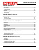
TABLE OF CONTENTS CHAPTER 6 – ANTENNAS Coaxial Cable Weather Proofing Coaxial Connectors Grounding Lightning Arrestors Reference Material Model 192C/F Outdoor Antenna Fixed Base Hardware Diagram Model 192CHP Outdoor Antenna Fixed Base Hardware Diagram Model 192M Outdoor Antenna Fixed Base Hardware Diagram Model 192MHP Outdoor Antenna Fixed Base Hardware Diagram Model 192C/F Indoor/Mobile Antenna Hardware Diagram Model 192CHP Mobile Antenna Hardware Diagram Model 192M Indoor/Mobile Antenna Hardware Diagram M
CHAPTER 1 STARTING OUT Computer Running Windows 95/98/NT ESTeem Model 192 Utility Software Windows Version BEFORE YOU START RS-232C Interface Cable (EST P/N AA061) Congratulations on your purchase of the ESTeem Wireless Modem! This section of the manual will describe the basic functioning and programming of the ESTeem to get your wireless network up as soon as possible.
CHAPTER 1 STARTING OUT 5. Double Click on the Setup.exe file to start the Utility Installation or extract the files to a directory for later installation. Running the Program 1. Select the ESTeem Utility Icon on Start>Programs menu. Figure 3 shows an example of the Main Utility Menu. STARTING OUT This section covers the basics setup and testing for the ESTeem wireless modem.
CHAPTER 1 STARTING OUT 8. 9. 10. 11. 12. 13. 14. 15. 16. 17. 18. T/E LED Press Set Serial Switches button. This window will • Link Connect/Disconnect Transmit LED • Auto Connect Enable configure the ESTeem’s RS-232/422/485 to operate at RS-232/422/485 • Serial Port Framing Error Setup Switches Receive LED the setting selected in step 7 to match the computer port setting. Follow the on-line guide to configure the data rate. Press Test ESTeem button.
CHAPTER 1 STARTING OUT each other and are now ready to proceed in programming them for your application. Press Exit to Main Menu and continue with the programming of the ESTeem for your application. BASIC ESTEEM PROGRAMMING Most of the ESTeem commands outlined in this section have been automatically input to the modem by the ESTeem Utility program. A few of the commands used most often in troubleshooting and programming are covered here.
CHAPTER 1 STARTING OUT Saving A Program A program is saved by typing in the SAVE command at the CMD: prompt. The programming variables that have been changed will be written to the non-volatile memory. The programming parameters will be loaded each time the modem is powered up or reset. Restoring Factory Defaults The ESTeem has a very simple procedure to restore the program variables in the unit to the factory default setting.
CHAPTER 2 MODES OF OPERATION The ESTeem has three major modes of operation, Command, Converse, and Transparent. This chapter of the manual describes each one of these modes. COMMAND MODE The COMMAND Mode (CMD: prompt) is the default mode that the ESTeem initially enters on power-up or after a hardware or software reset. From this mode the user can command or program the ESTeem. In this mode the user may access the various program commands to configure the ESTeem for the specific application.
CHAPTER 2 MODES OF OPERATION 3. Termination control timer. The termination control timer is enabled by the TERMC (on/off) command. When enabled, the termination timer starts from the time the last transmit buffer has been updated in the RS-232C port. If the termination timer expires before another character is received or transmitted, the contents of the ESTeem transmit buffer will be transmitted. The waiting time of the timer is defined by the TERMT variable (termination time).
CHAPTER 2 MODES OF OPERATION SEMI-TRANSPARENT MODE This mode should be utilized when sending a non-ASCII file and there is a possibility that the SENDPAC character could be contained in the transmitted data set. Perform the following prior to programming the ESTeem to initialize the unit to factory default settings: 1. Turn Bit 2, OFF on the RS-232C Setup Switch. 2. Reset the ESTeem. 3. TYPE FA . Please note the characters may or may not be echoed by the CRT.
CHAPTER 3 PROGRAMMING ESTEEM FEATURES Listed in this chapter are the major ESTeem features and programming examples on how to use them. These features are individual building blocks to solve your application needs. Remember your particular application may require one or more of these features enabled. DIGI-REPEATING The Repeater feature allows an ESTeem to relay its respective transmission or packet through a maximum of three ESTeems to increase the operating range of the unit.
CHAPTER 3 PROGRAMMING ESTEEM FEATURES GLOBAL BROADCAST Global broadcast is the ability of one ESTeem to transmit it's message to more than one ESTeem at one time. All ESTeems within radio range will receive the message whether or not they are connected to another ESTeem or in command or converse mode. You can put your ESTeem in Global by connecting or programming the SETC to address 255. Address 255 is a non-assignable unit address and is used by the ESTeem CPU to access this special mode.
CHAPTER 3 PROGRAMMING ESTEEM FEATURES AUTO CONNECT The Auto Connect feature allows the user to program the ESTeem to perform a CONNECT to another ESTeem when data is sent to the RS-232C communications port. To enable this feature perform the following from the COMMAND MODE: SETCON (1-255) = Address of destination ESTeem. Remember, you can use the Repeater routing (r1,r2,r3,da) or put the ESTeem in Global (address 255). SETCON is the set connect command. SA SAVE command.
CHAPTER 3 PROGRAMMING ESTEEM FEATURES MULTI-CONNECT The actual polling of the ESTeem must originate from the host device connected to the ESTeem using the CONNECT command to originate the initial connect and the COMMAND character to return from the CONVERSE mode to the COMMAND mode. The first time around the pole a CONNECT data packet (RF transmission) will be initiated. When a link is established, it is held internally in the ESTeem connect table.
CHAPTER 3 PROGRAMMING ESTEEM FEATURES REMOTE PROGRAMMING The Remote Programming feature allows the user to remotely program ESTeems in his network. When a connection has been made with the remote ESTeem the RPG: prompt will be displayed showing that you are now in the COMMAND mode of that remote ESTeem. To enable this feature perform the following from the COMMAND MODE: PROG (1-254) Note: Address of destination ESTeem. You can also use the Repeater routing (r1,r2,r3,da) to reach the destination ESTeem.
CHAPTER 3 PROGRAMMING ESTEEM FEATURES HARDWARE RING LINE (Factory Option) When the ESTeem establishes a CONNECT or link with another ESTeem (T/E Light on solid), pin 22 at the ESTeem RS-232C will change from a -15 vdc voltage state to a +15 vdc voltage state. The RING software command allows the user to change the output from a latched state to a pulsed state. To change the state of this line program the following from the COMMAND mode. Factory default = LATCH. RING = Latch.
CHAPTER 3 PROGRAMMING ESTEEM FEATURES USING THE INFRARED COMMUNICATIONS PORT The infrared (IR) communications port will allow you to program and interrogate the ESTeem without disconnecting the serial cable from the back of the modem. The IR port is located on the front panel of the ESTeem, above the T/E light. T/E IR Port S/N: TX Model 192S RX RESET PWR RE SET ANTE NNA To communicate from a computer to the ESTeem through the IR port you will need a copy of the ESTeem Utilities (Version 4.
CHAPTER 3 PROGRAMMING ESTEEM FEATURES UPDATING FLASH MEMORY The ESTeem Model 192 stores its operating system in flash memory that can be updated without returning the modem the to the factory. To upload the latest operating file, please contact Customer Support at 509-735-9092 or e-mail support@esteem.com to request the latest flash memory update file for your product. Once you receive the flash file from Customer Support, conduct the following steps to update the memory: 1. 2. 3.
CHAPTER 4 ESTEEM APPLICATION PROGRAMS Listed below are different application programs to aid the user in programming the ESTeem. TRANSPARENT AUTO-CONNECT This mode is used for a dedicated point to point application. The ESTeem will initiate the radio link when data is received by the RS-232/422/485 port. Perform the following prior to programming the ESTeem(s) to initialize the unit to factory default settings: 1. 2. 3. Turn Bit 2 OFF on the RS-232C Setup Switch. Reset the ESTeem. TYPE FA .
CHAPTER 4 ESTEEM APPLICATION PROGRAMS TRANSPARENT AUTO-CONNECT GLOBAL This mode is usually used for a point to multi-point applications when a customers devices include their own addressing protocol to communicate between devices. The ESTeem packet addressing and acknowledge protocol is defeated. All ESTeems will receive the data transmission. The 32 bit CRC error checking on received data is still enabled. This program is used in all ESTeems , the only difference is the unit addresses.
CHAPTER 4 ESTEEM APPLICATION PROGRAMS INTERACTIVE TERMINAL APPLICATION This program is used to connect a mainframe to a remote terminal. This setup is a typical point to point configuration with the AUTO-CONNECT feature enabled. Perform the following prior to programming the ESTeem(s) to initialize the unit to factory default settings: 1. 2. 3. Turn Bit 2 OFF on the RS-232C Setup Switch. Reset the ESTeem. TYPE FA . Please note the characters my not be echoed by the crt.
CHAPTER 5 RS-232C/422/485 INTERFACING DTE vs. DCE The ESTeem is configured as a Data Communication Equipment (DCE) device. The following signals are available at the RS-232C connector located at the rear of the unit.
CHAPTER 5 RS-232C/422/485 INTERFACING FLOW CONTROL The ESTeem can be enabled to support SOFTWARE or HARDWARE flow control. Software Flow Control Software flow control is enabled by the XSFLOW (on/off) command in the ESTeem. When XSFLOW is ON the ESTeem will respond to , (stop) and , (off) commands from the RS-232 port. The factory default setting is OFF. The default value for START is 17 (CTRL Q) and for STOP is 19 (CTRL S).
CHAPTER 5 RS-232C/422/485 INTERFACING MEMORY BUFFERS The ESTeem has a 4000 byte buffer on the TRANSMIT SIDE (outgoing data) and a 4000 byte buffer on the RECEIVE SIDE (incoming data). Transmit Buffer The outgoing data buffer will hold two data blocks before the ESTeem will enable its RS-232C hardware/software flow control on data coming into the modem if the network is busy. A data block in this example is a block of data that is defined by the PACKLENGTH or SENDPAC character which ever occurs first.
CHAPTER 5 RS-232C/422/485 INTERFACING RS-422/485 CONFIGURATION The ESTeem will support the requirements of the EIA Standard RS-422/485. This is a four (4) wire interface consisting of the TRANSMIT DATA (-), TRANSMIT DATA (+), RECEIVE DATA (-), AND RECEIVE DATA (+) or a two (2) wire interface using B (+) and A (-). These signals are available at the 25 pin RS-232C connector on the modem.
CHAPTER 5 RS-232C/422/485 INTERFACING RS-232C/422/485 COMRATE Tables The ESTeem Model 192 uses the COMRATE software command to set the communication port speed when Bit 1 on the RS-232 Setup Switches is in the ON position. The ESTeem Utility Program will calculate the required COMRATE value and download to the ESTeem in Step 3 of the Starting Out Menu or by selecting ESTeem Setup>Configure ESTeem Serial Port from the Terminal Emulation menu.
CHAPTER 6 ANTENNA SETUPS EST offers different types of antennas ranging from ¼ wave to 5/8 wave in physical size. The user choice is dependent on the application. Communications in the VHF and UHF bands are normally over "Line of Sight (LOS)". Looking from the antenna of one wireless modem you must be able to see the antenna of the wireless modem you wish to communicate with. If a large object obstructs the line of sight view it is unlikely that satisfactory communications will result.
CHAPTER 6 ANTENNA SETUPS WEATHER PROOFING COAX CONNECTIONS 1. 2. 3. Coat the threads of the connectors with silicone lubricant prior to assembly (See Note 1) and hand tighten. Care should be taken not to get any lubricant on the center conductor. Wrap the connector assembly with a vapor barrier patch for weather proofing (See Note 2), ensuring to overlap onto the coax cable approximately 1 1/2 inches. Apply a electrical coating (sealing agent) over the vapor barrier patch for added protection (See Note 3).
CHAPTER 6 ANTENNA SETUPS Revised: 13 Sep 05 6-3 EST P/N AA104
CHAPTER 6 ANTENNA SETUPS Revised: 13 Sep 05 6-4 EST P/N AA104
CHAPTER 6 ANTENNA SETUPS Revised: 13 Sep 05 6-5 EST P/N AA104