
User Manual Part 1


CHAPTER 1
STARTING OUT
Revised: 15 Oct 03 1-2 EST P/N AA104
5. Double Click on the Setup.exe file to start the Utility Installation
or extract the files to a directory for later installation.
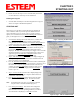
Running the Program
1. Select the ESTeem Utility Icon on Start>Programs menu. Figure 3
shows an example of the Main Utility Menu.
STARTING OUT
This section covers the basics setup and testing for the ESTeem
wireless modem. If this is your first experience with the ESTeem
wireless modems or you are unclear on how to set the frequency,
squelch, or test communication, the ESTeem Starting Out section will
guide you through the basics of wireless communication.
1. Select ESTeem Starting Out from the main menu. A window like
the one in Figure 4 will be displayed. If this is your first time
using the ESTeem wireless modems, select ESTeem Setup Guide for a
complete description of all ESTeem functions. Proceed to step 2.
2. Step 1 – Installing External Power window will be displayed (Figure 5).
Select either Find ESTeem or the model number of ESTeem you are
programming. The power requirements for that product will be
displayed. The ESTeem model AA174 power supply can be used with
all ESTeem products. If you are using the ESTeem in a solar power
application, press Calculate Solar Consumption button for the
Amp/Hours required. Press Go to Step 2 to continue.
3. Step 2 – ESTeem Familiarization window will be displayed (Figure 6).
This step will explain the connections to ESTeem Model 192 front
panel. See Figure 1 for a setup diagram.
4. Press the Front Panel Description button and a window containing the
ESTeem Model 192 front panel will appear (Figure 7). Press any one of
the buttons for a complete description of the item’s function. For
example, press the Power LED button and the description of the
power LED and its use will be displayed. Press Go To Step 3
button to proceed.
5. Step 3 – Serial Connection window will be displayed (Figure 8).
This step will help configure the computer and the ESTeem to
communicate with each other.
6. Press Display Cable Diagrams button and all serial pins to the
ESTeem Model 192 will be displayed. Press OK to continue.
Note: A standard 9-Pin serial port on a computer to ESTeem
interface cable is the ESTeem AA061 (Figure 1).
7. Press Change Port Settings. This window will configure the
communications port on your computer to operate with the
ESTeem modem. Select the operating parameters you wish or
set to the default of 19,200,N,8,1. Click OK to continue.
Figure 4: Starting Out Main Menu
Figure 5: Step 1 - Installing External Power
Figure 6: Step 2 – ESTeem Familiarization