CHAPTER 6 ANTENNA SETUPS Revised: 13 Sep 05 6-6 EST P/N AA104
CHAPTER 6 ANTENNA SETUPS Revised: 13 Sep 05 6-7 EST P/N AA104
CHAPTER 6 ANTENNA SETUPS Revised: 13 Sep 05 6-8 EST P/N AA104
CHAPTER 6 ANTENNA SETUPS Revised: 13 Sep 05 6-9 EST P/N AA104
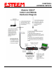
CHAPTER 6 ANTENNA SETUPS NOTE: For mobile applications the antenna must be mounted to maintain a minimum 50 cm. distance between the radiating element and any nearby person. When mounted on a vehicle it would be necessary to mount the antenna on the roof of the vehicle to ensure this minimum separation distance is maintained.
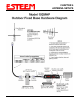
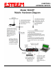
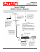
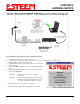
CHAPTER 6 ANTENNA SETUPS Programming The ESTeem Model 192 For SWR Measurements 1. 2. 3. 4. 5. 6. Configure the hardware as per the above diagram. Turn Switch 2 on the RS-232 Setup Switch (located on the rear of the ESTeem) to the OFF position. Reset the ESTeem (front panel push button). Install the ESTeem Utility on the PC hard drive as per instructions with the software. From Utility Main Menu (Figure 1) select the Terminal Emulation Mode.
CHAPTER 7 THEORY OF OPERATION INTRODUCTION ESTeem wireless modem products provide a "Wireless Solution" by eliminating conventional hardwiring of leased phone lines. All of the ESTeem models come with the industry standard RS-232C, RS-422, and RS-485 asynchronous communications ports to give the user a new dimension to "Local Area Networking". Our packet burst, frequency agile communications products allow the user to create a "Radio Area Network" of up to 255 users on a single frequency.
CHAPTER 7 THEORY OF OPERATION Well, very simply, that's how the ESTeem works. Once the address you're calling receives your packet, it's checked for accuracy. Accuracy is probably the single most important part of any communication device. The ESTeem uses Forward Error Correction (FEC) and a 32 bit Cyclic Redundancy Check (CRC) which is a very sophisticated method of checking the data integrity of the packet once its been received. The CRC insures data integrity greater than one part in one hundred million.
CHAPTER 7 THEORY OF OPERATION EFFECTIVE BAUD RATE The maximum input baud rate to the modem is 19,200 baud, asynchronous, full duplex, but this is misleading since the ESTeems actually communicate to each simplex over the RF link, at 19,200 bps (25 kHz channel spacing - Model 192C/F) or 9,600 bps (12.5 kHz channel spacing - Model 192C/F). The effective baud rate is a function of the above plus the packet length variable in the ESTeem (definable from 1 to 2000 bytes).
APPENDIX A FCC INFORMATION INFORMATION TO USERS WARNING: This equipment has been tested and found to comply with the limits for a Class A digital device, pursuant to Part 15 of the FCC Rules. These limits are designed to provide reasonable protection against harmful interference when the equipment is operated in a commercial environment.
APPENDIX A FCC INFORMATION Other Information Model 192C Model 192M 25 KHz Channel Spacing, 19,200 bps FCC Type Acceptance No: ENPESTEEM192 Emissions Designator: 17K6F1D 25 KHz Channel Spacing, 19,200 bps U.S.A. Type Acceptance: ENPESTEEM192M Emission Designator: 17K6F1D 12.5 KHz Channel Spacing, 9,600 bps FCC Type Acceptance No: ENPESTEEM192A Emissions Designator: 10K8F1D 12.5 KHz Channel Spacing, 9,600 bps U.S.A. Type Acceptance: ENPESTEEM192M Emission Designator: 10K8F1D 12.
APPENDIX A FCC INFORMATION FEDERAL COMMUNICATIONS COMMISSION FIELD OFFICES ALASKA 1011 E. Tudor Rd. Rm 240 Box 2955 Anchorage, AK 99510 HAWAII 300 Almoana Blvd. P.O. Box 50023 Honolulu, HI NEW YORK 1307 Federal Building 111 W. Huron Buffalo, NY 14202 CALIFORNIA 7840 El Cajon Blvd Suite 405 La Mesa, CA 92041 ILLINOIS 3935 Federal Bldg 230 S. Dearborn Chicago, IL 60604 201 Varick Street New York, NY 10014 3711 Long Beach Blvd Suite 501 Long Beach, CA 90807 LOUISIANA 1009 Edw Hebert Bldg.
APPENDIX B SPECIFICATIONS Model 192C/CHP/F/M Overall Specifications SWITCHES: • • CPU Reset RS-232C/422/485 Setup DATA BUFFERS: • • Transmit 4000 bytes Receive 4000 bytes POWER REQUIREMENTS: Models 192C & 192F • LED INDICATORS: • • • • • • Power On Receiver Carrier Detect Transmitter Enable Link Connect/Disconnect Auto Connect Enabled RS-232C/422/485 Framing Error FLOW CONTROL: • DATA TRANSMISSION PROTOCOL: • I/O - CONNECTORS: • • • Asynchronous Full Duplex, RS-232C, RS-422 and RS 485 with 25 Pin
APPENDIX B SPECIFICATIONS Model 192C/CHP/F/M/MHP Overall Specifications Frequency Range Frequency Selection Frequency Stability Frequency Selectability RF Data Rate Transmitter Modulation Transmitter Deviation Transmitter RF Power Output Transmitter Duty Cycle Transmitter Spurious & Harmonics Transmitter Rise Time Receiver Sensitivity: Receiver Spurious & Image Rejection Receiver Squelch Sensitivity Receiver Adjacent Channel Rejection Receiver Modulation Acceptance: Receiver Base Bandwidth: Transmit/Rece
APPENDIX B SPECIFICATIONS Model 192C/CHP/F/M/MHP Overall Specifications ESTeem Model 192F Frequency Range Frequency Selection Frequency Stability Frequency Selectability 400 to 420 MHz Digitally Synthesized - Software Selectable +/- 1 ppm 6.
APPENDIX B SPECIFICATIONS Model 192C/CHP/F/M/MHP Overall Specifications Frequency Range Frequency Selection Frequency Stability Frequency Selectability RF Data Rate ESTeem Model 192M ESTeem Model 192MHP 150 to 174 MHz Digitally Synthesized - Software Selectable +/- 2.5 ppm 6.25KHz 19,200 bps @ 25 KHz Channel Spacing U.S.A. Type Acceptance: ENPESTEEM192M Emission Designator: 17K6F2D 150 to 174 MHz Digitally Synthesized - Software Selectable +/- 2.5 ppm 6.25KHz 19,200 bps @ 25 KHz Channel Spacing F.C.C.
APPENDIX B SPECIFICATIONS Model 192C/CHP/F/M/MHP Case Diagram Revised: 13 Apr 05 APX B- 5 EST P/N AA104
APPENDIX B SPECIFICATIONS Model 192C/CHP/F Antenna Specifications Model No: Antenna Type: Applications: Frequency: Polarization: Impedance: Gain: VSWR: Front To Back Ratio: Horizontal Beamwidth: Vertical Beamwidth: Antenna Material: Mounting Hardware: Antenna Connector: Antenna Envelope: Weight: Model No: Antenna Type: Applications: Frequency: Polarization: Impedance: Gain: VSWR: Front To Back Ratio: Horizontal Beamwidth: Vertical Beamwidth: Antenna Material: Mounting Hardware: Antenna Connector: Antenna
APPENDIX B SPECIFICATIONS Model 192C/CHP/F Antenna Specifications Model No: Antenna Type: Applications: Frequency: Polarization: Impedance: Gain: VSWR: Front To Back Ratio: Horizontal Beamwidth: Vertical Beamwidth: Antenna Material: Mounting Hardware: Antenna Connector: Maximum Power Input: Antenna Envelope: Windload (RWV): Weight: Revised: 13 Apr 05 AA202C & AA202F Directional, DC grounded, 5 element yagi. Fixed base.
APPENDIX B SPECIFICATIONS Model 192M/MHP Antenna Specifications Model No: Antenna Type: Applications: Frequency: Polarization: Impedance: Gain: VSWR: Front To Back Ratio: Horizontal Beamwidth:n/a Vertical Beamwidth: Antenna Material: Mounting Hardware: Antenna Connector: Antenna Envelope: Weight: Model No: Antenna Type: Applications: AA19M Omni-Directional, ½ Wave over ¼ Wave. Mobile Mount. 150 to 174 MHz Vertical 50 ohms Unity < 1.5 to 1 n/a 60 degrees Rubber duck whip. Magnetic base.
APPENDIX B SPECIFICATIONS Model 192M/MHP Antenna Specifications Model: AA202M Antenna Type: Directional, 3 Element Yagi, DC Ground Applications: Fixed base mounting. Frequency: 150 to 174 MHz Polarization: Vertical or Horizontal Impedance: 50 ohms Gain: 7.1 dB VSWR: < 1.5 Front To Back Ratio: 17 dB Horizontal Beamwidth:72 degrees Vertical Beamwidth: 57 degrees Antenna Material: 6061-T6 Aluminum Boom Diameter: 7/8 in.
APPENDIX C ESTeem MESSAGE TABLES ESTeem Command Error Messages Listed below are the ESTeem Command Error Messages and their definitions. To receive these messages, TYPSYSTEM must be ON (See Appendix D, Definitions). All System Status Message have a bell (O7H or CTRL G) preceding the message except when Messform is ON. If MESSFORM = OFF Line A will be displayed. If MESSFORM = ON Line B will be displayed. 1.
APPENDIX C ESTeem MESSAGE TABLES ESTeem System Status Messages Listed below are the ESTeem System Status Messages and their definitions. To receive these messages, TYPSYSTEM must be ON (See APPENDIX D, DEFINITIONS). All System Status Messages have a bell (O7H or CTRL G) preceding the message except when Messform is ON. If Messform = OFF Line A will be displayed. If Messform = ON Line B will be displayed. 1. A B "CONNECTED TO XX" SSO1-xx 7.
APPENDIX C ESTeem MESSAGE TABLES ESTeem System Error Messages Listed below are the ESTeem System Error Messages and their definitions. To receive these messages, TYPSYSTEM must be ON (See APPENDIX D, DEFINITIONS). All System Status Messages have a bell (O7H or CTRL G) preceding the message except when Messform is ON. If Messform = OFF Line A will be displayed. If Messform = ON Line B will be displayed. 1.
APPENDIX D SOFTWARE COMMANDS Listed below are the software commands and their factoy default setting.
APPENDIX D SOFTWARE COMMANDS Listed below in alphabetical order are the definitions of the ESTeem software commands. A_BCTRL This function enables the Allen Bradley controller protocol. For further details reference the EST Engineering Report on Allen Bradley controller interfacing. ON: OFF: Enabled. Disabled. Factory default = OFF. ADDress (1-255) The command defines the ESTeem source address. The default value is whatever address has been stored in nonvolatile memory.
APPENDIX D SOFTWARE COMMANDS COMMand (0-255) This command specifics the value (in decimal) of an ASCII character used to return the ESTeem to COMMAND MODE. If the COMMAND character is read by the ESTeem when in the CONVERSE MODE, the modem will exit to the COMMAND MODE. A value of 0 in this command will disable the function. Factory default = $O3 (Hex) or CTRL-C. COMRate (0-255) This command defines the RS-232/422/485 configuration when Switch 1 on the RS-232 Setup Switches is engaged.
APPENDIX D SOFTWARE COMMANDS DNP (On/Off) This command command enables the DNP protocol. For further information reference Engineering Report 21-004. Factory default = Off. On: Enabled Off: Disabled DTR_enab (on/off) The DTR enable command. This command, when enabled, allows the ESTeem modem to monitor pin 20 of the RS-232C connector in regards to the status of an external device connected to it. ON: Enables monitoring the DTR signal on pin 20 of the RS-232C connector.
APPENDIX D SOFTWARE COMMANDS GE_CTRL This command enables the General Electric controller protocol. For further information please reference the EST Engineering Report on General Electric controller interfacing. ON: OFF: Enabled. Disabled. Factory default = OFF. HElp HELP switches are: HELP Displays this Help menu. HELP ALL Displays All commands switches and arguments. HELP CHANGE Displays only the commands that are changed from factory default.
APPENDIX D SOFTWARE COMMANDS MESSform (on/off) When enabled all of the system status and error messages will be in a formatted form. "xx" indicates what error or message (See Error Messages and System Status Messages). EMxx SExx SSxx SSxx-xxxx ON: Enabled. OFF: Disabled. [ESTeem Error Messages] [System Error Messages] [System Status Messages] [System Status Message W/Returned Value] Factory default = OFF.
APPENDIX D SOFTWARE COMMANDS MULTID (on/off) This command when enabled allows the ESTeem User to send data to another ESTeem from the CONVERSE MODE by specifying the routing address before the data. ON: OFF: Enabled. Disabled. Factory default = OFF. Example Of Transmitted Data: [001]DATA Routes data to an ESTeem addressed 1. [100,200,250,1]DATA Routes data to an ESTeem addressed 1 via ESTeems addressed 100, 200, and 250. This replaces using the CONNECT command from the COMMAND Mode.
APPENDIX D SOFTWARE COMMANDS PLC_MAST (on/off) The programmable logic controller (PLC) command. ON: OFF: When enabled, the ESTeem modem will identify the desired route from the master PLC message. The ESTeem modem will only identify the PLC master route if the master command is enabled in the PLC. The ESTeem modem will be configured as to interface to a slave PLC. Factory default = OFF.
APPENDIX D SOFTWARE COMMANDS REMprog (on/off) This command will disable the ESTeem from being remotely programmed by any another ESTeem. ON: OFF: Enabled. Disabled. Factory default = ON. RESet The software reset command for the ESTeem. The execution of this command resets the internal electronics in the ESTeem. RESTore The restore command. The execution of this command restores the ESTeem command variables and switches configurations stored in nonvolatile memory. RETry (1-255) The retry command number.
APPENDIX D SOFTWARE COMMANDS RXEnd (1-255) This command defines the time (milliseconds) to wait after the last character is received before reinitializing the receiver. Factory default = 1. RXSIGNAL (on/off) This command enables the signal to noise ratio meter output. Output level varies from 0 to 248 (248 being the highest reading). ON: OFF: Enabled. Disabled. Factory default = OFF. SAve The save command. The execution of this command stores the current command values and switches.
APPENDIX D SOFTWARE COMMANDS S/N Serial Number command. When executed from the Command Model will output the ESTeem serial number of the unit that is defined at the time of manufacturer. SQDCTRL (on/off) This function enables the Square D controller protocol. For further detail Reference the EST Engineering Report on Square D controller interfacing. Factory default = OFF. SQDADD (1-254) This function is used with the SQDCTRL command to control the address fence when using SQ-D Network Interface Modules.
APPENDIX D SOFTWARE COMMANDS TYPerr (on/off) This command enables the Communication Error Messages. ON: Enabled. OFF: Disabled. Factory default = OFF. TYPSyste (on/off) This command enables the System and Error Message Commands. ON: OFF: Enabled. Disabled. Factory default = ON. VERSION This command will display the current software version being used by the ESTeem. XHflow (on/off) This command enables hardware flow control. ON: OFF: Enabled. Disabled. Factory default = OFF.