
User's Manual


CHAPTER 5
EXAMPLE CONFIGURATIONS
Revised: 23 Jan 08 5-17 EST P/N AA107G
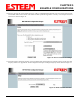
9. Select the frequency channel of operation. All Access Points in the same Repeater Peer network need to be on the same radio
frequency channel. See Appendix D – Radio Configuration for help in selecting the frequency channel. Reference Figure 28.
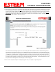
10. The Repeater Peer Table identifies which Model 195Eg’s will bridge wireless Ethernet communication. Only other Access
Point Repeaters need to be listed not
the Model 195Eg’s in client modes. Looking at the system layout in Figure 1 and what we
discussed in Example 1, both the Plant Network’s 195Eg and the Remote Building’s 195Eg will be listed by their wireless
(WLAN) MAC
(Figure 29). There is only a single radio connection path to the other two 195Eg’s in the network. The path
cost only effects redundant links in the network (not applicable to the repeater) and will be left at default. Enter the WLAN
MAC addresses for the other two Access Points and press the Next button to continue.
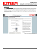
11. Select Commit Changes to write the programming to Flash memory and reboot the Model 195Eg. When the reboot process has
completed (approximately 30 seconds) the modem will be ready to place in operation.
Figure 28: Channel Configuration
Figure 29: Repeater Configuration