
User's Manual

CHAPTER 5
EXAMPLE CONFIGURATIONS
Revised: 23 Jan 08 5-2 EST P/N AA107G
Documentation
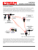
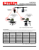
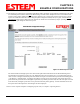
The first step when configuring your wireless system will be to document each Model 195Eg used in the network. The following is
an example of the System Configuration Table (Chapter 2 – Starting Out) completed for the two example applications:
Modem_ID(Name)
/Operating Mode
Serial Number IP Address Ethernet MAC WLAN MAC
Plant Network
AP_Router
E-14001 Ethernet 172.17.2.1
Wireless 172.16.2.1
00:04:3f:00:09:02 00:04:3f:00:09:01
Repeater
AP_Bridge
E-14002 Bridge 172.16.2.5 00:04:3f:00:09:06 00:04:3f:00:09:05
Remote Building
AP_Bridge
E-14003 Bridge 172.16.2.10 00:04:3f:00:09:11 00:04:3f:00:09:10
Forklift
EtherStation
E-14004 N/A 00:04:3f:00:09:21 00:04:3f:00:09:20
Truck #1
Station Router
E-14005 Wireless 172.16.2.20
Ethernet 172.18.1.1
00:04:3f:00:09:26 00:04:3f:00:09:25
Truck #2
Station Masquerade
E-14006 Wireless 172.16.2.30
Ethernet 172.19.1.1
00:04:3f:00:09:31 00:04:3f:00:09:30
Table 1: Example System Configuration Table
Mobile
PLC
Station Router Mode
Voice over IP
Mobile Vehicle #1
Multiple Ethernet Devices
Example #5
S/N: 14005
Mobile Vehicle #2
Multiple Ethernet Devices
Example #6
S/N: 14006
Station Masquerade Mode
Remote PC
GPS
10/100BaseT
Access Point Bridge
with Repeater
Feature Enabled
Ethernet Wired LAN
Network
Router
(Required)
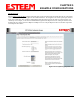
Figure 2: Programming Example #2 Diagram