
User's Manual

CHAPTER 5
EXAMPLE CONFIGURATIONS
Revised: 23 Jan 08 5-9 EST P/N AA107G
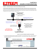
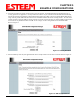
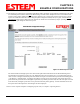
12. The Repeater Peer Table (Figure 15) identifies which Model 195Eg’s will bridge wireless Ethernet communication. Only other
Access Point Repeaters need to be listed not
the Model 195Eg’s in client modes. Multiple links to the same destination will
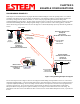
provide a backup pathway (Mesh Network) if the primary pathway is lost. Looking at the system layout in Figure 1, both the
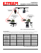
repeater site and the direct link will be listed. Using the System Configuration Table (Table 1) as a guide, enter the Wireless
(WLAN) MAC
address for the 195Eg’s that will communicate with the Access Point Router (Example 1) starting with the
primary repeater path through the stand-alone repeater.
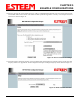
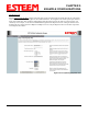
The communication link through repeater site is the best radio path from the Plant Network to the Remote Building and we
want this link to be the primary repeater route. The 195Eg follows the same networking “rules” as any other Ethernet device
and if we made no changes to the default path cost of 100 the lowest path cost would be directly to the Remote Building (Direct
= 100, Repeater = 200 (100+100)). To configure the 195Eg to select the repeater as the primary radio path, the direct link’s
path cost must be greater than the cost through the repeater link (any number greater than 200). We will set the path cost at 201
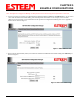
for the direct link, making the repeater link a lower path cost and thus the primary pathway. Press the Add button to enter the
first repeater link to the Repeater Peer List and Figure 16 will be displayed.
Note: For a more complete description on configuring repeater routes, see Chapter 6 – Repeating Features.
Figure 15: Blank Repeater Table