
User's Manual

CHAPTER 5
EXAMPLE CONFIGURATIONS
Revised: 23 Jan 08 5-27 EST P/N AA107G
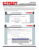
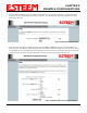
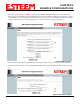
5. Refer to the IP address in Table 1 and enter the ethernet IP address and IP netmask. Reference Figure 48.
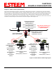
Note: When configuring the Ethernet devices connected to the Station Router 195Eg, the ethernet IP address will be their
Gateway address (Figure 37).
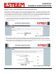
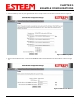
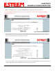
6. All IP requests for the Ethernet devices connected to the 195Eg Station Router (Example #5) will need to be resolved by the
Network Router (Figure 37). Enter the default route (Gateway) IP address for the Network Router in the 195Eg. Enter any
DNS server information and press the Next button. Figure 49.
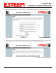
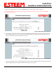
7. Select Commit Changes to write the programming to Flash memory and reboot the Model 195Eg. When the reboot process has
completed (approximately 30 seconds) the modem will be ready to place in operation.
Figure 48:Wired Ethernet Interface
Figure 49:Default Route (Gateway) and DNS Input