
User's Manual

CHAPTER 5
EXAMPLE CONFIGURATIONS
Revised: 23 Jan 08 5-21 EST P/N AA107G
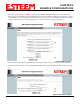
Example 5 – Mobile Vehicle #1 (Station Router)
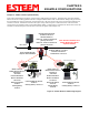
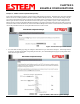
Review the Example Diagram #2 (Figure 2) and locate the 195Eg marked as Example 5. This ESTeem is connected to multiple
Ethernet devices in a mobile application and will be configured Station Router mode. In this mode the 195Eg’s will gain access to
the wireless Ethernet canopy created by the Access Point and act as the router between the devices connected to the Ethernet port
and wireless network. Each of these networks will require a unique subnet to operate. If Ethernet devices on the wired LAN
network want to access Ethenet devices on the Station Router 195Eg, a network router is required on the wired LAN to resolve the
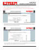
IP conflict created by having the wired and wireless networks on separate subnets (Figure 37).
HUB or Switch
Network Router (Required)
IP Address 172.16.1.6
Netmask 255.255.0.0
Routes for 172.18.X.X network use
gateway 172.16.2.20
Routes for 172.19.X.X network use
gateway 172.16.2.30
Note: Wireless Networks and
Station Modes Must Be on
Separate Subnets
Bridge IP Address = 172.16.1.1
Netmask = 255.255.0.0
Default Route = 172.16.1.6
Mobile
PLC
Station Router Mode
Voice over IP
Mobile Vehicle #1
Multiple Ethernet Devices
Example #5
S/N: 14005
Netmask 255.255.0.0
Wireless IP Address
172.16.2.20
Ethernet IP Address
172.18.1.1
Gateway(Route)
172.16.1.6
Mobile Vehicle #2
Multiple Ethernet Devices
Example #6
S/N: 14006
Netmask 255.255.0.0
Wireless IP Address
172.16.2.30
Ethernet IP Address
172.19.1.1
Gateway(Route)
172.16.1.6
Station Masquerade Mode
Remote PC
GPS
Access Point Bridge with
Repeater Feature Enabled
Connected Ethernet Devices
172.18.X.X
Gateway (Route) = 172.18.1.1
Connected Ethernet Devices
172.19.X.X
Gateway (Route) = 172.19.1.1
Figure 37: Station Router IP Addressing Diagram