Touchscreen User Manual Revision B C o p y r i g h t © 2 0 1 0 E le c tr o n i c T h e a t r e C o n t r o l s , I n c . All Rights reserved. P r o d u c t in f o r m a t i on a n d s p e c i f i c a t i o n s s u bj e c t t o c h a n g e .
Table of Contents Introduction . . . . . . . . . . . . . . . . . . . . . . . . . . 1 Touchscreen Specifications . . . . . . . . . . . . . . . . . . . . . . . . . . . . . . . .1 Warnings and Notice Conventions . . . . . . . . . . . . . . . . . . . . . . .2 Contacting ETC . . . . . . . . . . . . . . . . . . . . . . . . . . . . . . . . . . . . . .2 Overview . . . . . . . . . . . . . . . . . . . . . . . . . . . . 3 Power and Data Connections . . . . . . . . . . . . . . . . . . . . . . . . . . . . . .
Introduction Welcome to the Paradigm Touchscreen user’s guide. This manual contains the procedures for setup of the Paradigm Touchscreens including theme file loading, menu navigation, touchscreen calibration, timed events editing, and cleaning instructions. Reference the related Paradigm Touchscreen Installation or Setup Guide for information on installation and hardware setup.
Warnings and Notice Conventions These symbols are used in ETC documentation to alert you to danger or important information: Note: Notes are helpful hints and information that is supplemental to the main text. CAUTION: A Caution statement indicates situations where there may be undefined or unwanted consequences of an action, potential for data loss or an equipment problem.
Overview Power and Data Connections Paradigm Wall Mount and Rack Mount Touchscreen stations are designed to connect to the Paradigm Control system using either LinkConnect or NetConnect for power and data. Note: The ground connection to the Wall Mount and Rack Mount Touchscreen is provided through the RJ11 connection, regardless of the data connection type, LinkConnect or NetConnect.
Touchscreen Inputs, Outputs and Indicators Each model of the Touchscreen has an I/O panel that includes an USB port, SD card slot, and a selection of indicators and service pins. The indicator and service pin selections vary depending on the model of Touchscreen. The Portable Touchscreen I/O panel is revealed behind a door on the bottom of the unit.
Status • “Reset” button - when pressed, resets the LCD software causing a reboot and service pin message to the connected processor. • “Mode” button - press once for “Setup menu”. Press and hold four seconds to calibrate the Touchscreen. • “PoE” LED- illuminates solid when Power over Ethernet is present (NetConnect only). • “Aux” LED - illuminates solid when the Touchscreen is powered (LinkConnect only). • “Act” LED - reserved for future development.
Image Format ControlDesigner software supports the following image formats for use on page backgrounds and button states: Note: • Portable Network Graphic (.png). • Graphical Interchange Format (.gif). • JPEG Image File (.jpg). Excluding compressed .jpg files as they will not display on the Paradigm Touchscreen. • X11 Pixmap Graphic (.xpm) ETC recommends that all images used in a configuration file for the Paradigm Touchscreen be a .
Touchscreen Setup Menu How a Touchscreen behaves when it is powered depends on two things: 1 Is a ControlDesigner configuration file loaded onto the Touchscreen? 2 Is the Touchscreen bound/connected with the P-ACP? When both of these are true, and the Touchscreen is powered, the configuration will load to the home page of the selected configuration.
Setup Menu Pressing the [Setup] button on the default page displays the About tab of the Touchscreen setup menu. Alternatively, you can access the setup menu by pressing the “Mode” pin on the Touchscreen I/O panel. See “Touchscreen Inputs, Outputs and Indicators” on page 4. Each tab of the setup menu displays a footer of buttons including [Service Pin], [Ok] and [Cancel].
• Watchdog: displays the status of the Watchdog tool. Note: Watchdog is a service that monitors Touchscreen activity and will automatically reboot the device in the event it would suffer a crash or lockup. Watchdog should be “enabled” unless instructed otherwise by ETC Technical Services. Screen tab The “Screen” tab provides user settings for the Touchscreen including: • Backlight Level: a level bar is provided to set the relative brightness of the Touchscreen backlight.
• Note: If the sensor registers any moving or stationary objects within this range, it will “wake” the station from its sleeping state and reset the backlight timeout and the station inactivity timer as set in ControlDesigner. Be aware of stationary objects (such as rack doors) that remain within the sensing range as it may interfere with the function of the sensor. In these applications, it is best practice to disable the Proximity Sensor.
S o u n d ta b The “Sound” tab provides a volume control for the master volume level of the Touchscreen’s built-in speaker. Comms tab The “Comms” tab provides read-only information pertaining to which Paradigm Architectural Control Processor (P-ACP) the Touchscreen is connected over the Paradigm control network.
• Connection Type: this is the type of connection that is made to the P-ACP. Options include “Ethernet” which is NetConnect, or “Lon” which is LinkConnect. Note: This is a very useful tool when troubleshooting your communication connection between the Paradigm Touchscreen and your Paradigm control system. When a Paradigm Touchscreen is connected by NetConnect, the IP address of the P-ACP will display as the “Server Address”.
Protected Features and Tabs The “Files”, “Network” and “System” tabs as well as the “Timed Events” feature on the “Config” tab are protected by passcode and should be used only by trained personnel. Typically these displays are accessed only during system commissioning. Pressing any of the tab names will display a keypad for passcode entry. Note: Enter your four digit passcode _ _ _ _ to access these menus. These protected tabs should be accessed only by trained personnel.
Adding a new event and editing an event are similar in process. Add Event 14 Step 1: Press the [Add] button, a “New Timed Event” configurator will display. Step 2: Specify the “Start Time”. Pressing the default [Time of Day] button displays a list of available start times including; “Time of Day”, “Sunrise”, and “Sunset”. Press to select the option. Depending on the selection, additional options may display: • If “Time of Day” is selected, additional selection for a “Start Time” is required.
Step 3: Specify the “End Time”. The options for “End Time” are similar to the “Start Time” except “Duration” is now an option. When “Duration” is the selected “End Time”, you will also be required to specify the hours and minutes the event should run from its start time. Step 4: If an override has been created for the Timed Event, select the override from the options.
• Additional settings are provided depending on the “Recurrence Type” selected. For example, if “Weekly” is selected, the following options display - Step 7: Press [Next] then select the drop down selection located next to “Start Action” to display available options. Step 8: Press to select the option from the list. Notice the ability to scroll to more options using the scroll bar on the right. Depending on the selection, more options may display for setting on the “Start Action” page.
Files tab The “Files” tab allows you to view, modify, and delete the configuration and theme files that are currently loaded on the Touchscreen. As well, you are provided access for uploading and downloading the configuration and theme files from/to removable media such as an SD card or USB key. See “Ports” on page 4.
Saving and L oading Conf iguration Files Saving and loading configuration and theme files is simple. Step 1: To begin, you must have an USB key or SD card (your choice) inserted into the port receptacle of the Touchscreen. Step 2: Select either [Config] or [Theme] (whichever file type you want to transfer). Step 3: If saving a file to removable media select the file from the list and press [Save to]. If loading a file from removable media, press [Load From].
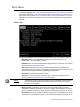
IP Addressing Two “IP Addressing” modes are available for use with the Touchscreen; Manual and Automatic. • Manual Mode - in manual address mode the IP address and settings are user configured. To change any portion of the address, simply touch inside the field you wish to modify. A numeric keypad will display for edit of the selected field. Make the modifications to the selected field then select another field for edit as necessary.
• Firmware: the Touchscreen co-processor firmware version. Reload Firmware The [Reload Firmware] button is provided as a tool to load new firmware. Firmware is loaded to the Touchscreen from removable media. Note: The Touchscreen firmware file is stored in the LightDesigner installation directory firmware folder (the file is titled “firmware.pts”). Save the file to the root directory of a USB or SD card for loading onto the Paradigm Touchscreen.
Cleaning the Display Use a dry micro fibre or lint-free cloth to clean any finger prints and oils from the LCD. Do not use any chemical or water-base solution as they will damage the display.
Corporate Headquarters 3031 Pleasant View Road, P.O.