Source Four® Fresnel User Manual Rev A C o p y r i g h t © 2 0 1 1 E le c tr o n i c T h e a t r e C o n t r o l s , I n c . All Rights reserved. P r o d u c t in f o r m a t i on a n d s p e c i f i c a t i o n s s u bj e c t t o c h a n g e .
E T C pe r m i t s t h e r e p r o d u c t i o n o f m a t e r i a l s i n th i s m a n u a l o n l y f o r n o n - c o m m e r c i a l p u rp o s e s . A l l o t h e r r i g h ts a r e reserved by ETC. E T C i n t e n d s t h i s d o c u m e n t , w h e t h e r p r i n t ed o r e l e c tr o n i c , to b e p r o v id e d i n i t s e n ti r e t y .
Table of Contents Basic Assembly . . . . . . . . . . . . . . . . . . . . . . . . . . . . . . . . . . . . . . . . .1 Lamp Information . . . . . . . . . . . . . . . . . . . . . . . . . . . . . . . . . . . . . . . .2 HPL Lamp Table . . . . . . . . . . . . . . . . . . . . . . . . . . . . . . . . . . . . .2 Installing and Replacing the Lamp. . . . . . . . . . . . . . . . . . . . . . . .3 Field Angle Adjustment . . . . . . . . . . . . . . . . . . . . . . . . . . . . . . . . . . .6 Accessory Holder . . . . . . . .
ii
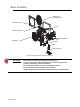
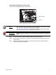
Basic Assembly Safety screen (CE markets only) Color frame holder Yoke Accessory holder door Field angle adjustment knob Fresnel lens Lamp door Lamp Lamp holder base Figure-1 Source Four Fresnel fixture components. WARNING: Please note the following safety warnings before use: Do not use this fixture with a damaged power lead. If the power lead (cordset) is damaged, it must be replaced. Do not mount the fixture on or near combustible surfaces. Do not operate the fixture without a lens installed.
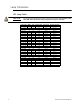
Lamp Informati on HPL Lamp Table CAUTION: Do not use lamps other than the HPL in Source Four fixtures. Use of lamps other than HPL will void UL/cUL safety compliance and your warranty. Lamp code Watts Volts Initial Lumen Color temp.
Installing and Replacing the Lamp A lamp must be installed before you use the fixture. Lamp door latch Lamp door Figure-2 Lamp door on bottom of the fixture. Note: Verify that the HPL lamp you intend to install is suitable for your facility’s voltage; 115-, 120-, 230-, and 240-volt HPL lamps are available. See HPL Lamp Table, page 2. Operating HPL lamps above their rated voltage reduces lamp life and can cause premature lamp failure.
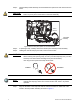
Step 4: Twist the lamp socket assembly counterclockwise one quarter turn and remove from the fixture. CAUTION: The socket assembly remains connected to the fixture by means of its electrical leads. Do pull or place undue stress on the wired assembly. Turn to remove Lamp holder assembly Figure-3 Remove lamp with quarter turn counterclockwise. Step 5: If replacing a lamp, carefully remove the old lamp from the lamp socket assembly.
Step 8: Push down on the lamp base until the lamp seats firmly. When properly installed, the top of the lamp’s base will be even with the top edges of the retention brackets. CAUTION: Step 9: Improperly installed lamps and lamp holder assemblies cause premature lamp failure and socket problems. Reinstall the lamp holder assembly into its socket in the fixture so that the arrow points towards the “unlock” icon on the socket.
Field Angle Adjustment You can adjust the field angle of the fixture from 20 to 65° with the field angle adjustment knob. Step 1: Lift the locking lever to unlock the field angle adjustment knob. Field angle adjustment knob Locking lever Figure-4 Field angle adjustment knob and locking lever. CAUTION: Step 2: The focus knob does not rotate 360°. Do not attempt to exceed limit. Do one of the following. • To reduce the field angle, turn the focus dial counterclockwise.
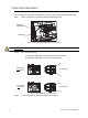
Accessory Holder The accessory holder is equipped with two slots and a locking door that prevents color frames and accessories from falling out. Accessory holder locking door Figure-6 Accessory holder door in the open position. . WARNING: Make sure all color frames and accessories are locked in position with the accessory door before hanging the fixture.
Step 1: Release the accessory holder door by pressing in on the latches located on each side of the door. Latch Lift front to open Latch Accessory slots Figure-8 Accessory holder door releases. Step 2: Insert the color frame or accessory. Step 3: Press down on the two accessory door latches to lock the door in place. Note: Use only color frames or accessories with a 7.5 inch mounting flange.
Yoke Balance Point Adjustment The yoke mounting position can be adjusted on the fixture to accommodate varying weights of different accessories. For example, move the yoke balance point forward (toward the lens) to balance the additional weight of a color scroller and barndoor assembly in the accessory slot. Step 1: Loosen the nuts on both sides of the yoke assembly, being sure to steady the fixture with the handle on the rear of the unit.
Replaci ng the Lens Replace the lens if it becomes cracked or badly scratched. CAUTION: Never operate the fixture without a lens in place. WARNING: Unplug the fixture and allow it to cool down before attempting to change a lens. Removing the lens Step 1: Place the fixture on a flat, stable work surface. Do Not remove or install the lens with fixture hanging. Step 2: Tilt the front of the fixture down at least 45°.
Figure-11 Removing the lens. Step 5: Carefully remove the lens. Installing the lens Note: Do not leave finger prints on the lens. Handle the lens with a soft, clean cloth. Step 1: Position the fixture with the front of the unit (lens side) facing you, and tilted slightly upward. Step 2: Hold the lens by the edge and position it so the stepped side faces the front of the fixture.
Corporate Headquarters 3031 Pleasant View Road, P.O.