
User's Manual

EL-2606
Electronics Line 3000 Ltd.: 2 Granit Street, Kiryat Arieh, POB 3253, Petah Tikvah 49130 Israel. Tel: (972-3) 918-1333, Fax: (972-3) 922-0831
USA: 5637 Arapahoe Avenue, Boulder, Colorado 80303. Tel: (800) 683-6835, Fax: (303) 938-8062
UK: Unit 7, Leviss Trading Estate, Station Road, Stechford, Birmingham B33 9AE. Tel: (44-121) 789-8111, Fax: (44-121) 789-8055
France: ZI-61, rue du Marché Rollay, 94500 Champigny-Sur-Marne. Tel: (33-1) 45.16.19.20, Fax: (33-1) 45.16.19.29
Note: This equipment has been tested and found to comply with the limits for a Class B digital device, pursuant to part 15 of the FCC Rules. These limits are
designed to provide reasonable protection against harmful interference in a residential installation. This equipment generates, uses and can radiate radio frequency
energy and, if not installed and used in accordance with the instructions, may cause harmful interference to radio communications. However, there is no guarantee
that interference will not occur in a particular installation. If this equipment does cause harmful interference to radio or television reception, which can be determined by
turning the equipment off and on, the user is encouraged to try to correct the interference by one or more of the following measures:
1. Reorient or relocate the receiving antenna, 2. Increase the separation between the equipment and the receiver, 3. Connect the equipment into an outlet on a circuit
different from that to which the receiver is connected, 4. Consult the dealer or an experienced radio/TV technician for help.
Warning: Changes or modifications to this equipment not expressly approved by the party responsible for compliance (Electronics Line 3000 Ltd.) could void the
user’s authority to operate the equipment.
All data is subject to change without prior notice/Ces spécifications techniques sont sujettes à modifications sans avis préalable/Todos estos datos están sujetos a cambio sin preaviso alguno.
In no event shall Electronics Line 3000 Ltd. (EL3K) be liable for an amount in excess of EL3K.’s original selling price of this product, for any loss or damage whether direct, indirect, incidental,
consequential or otherwise arising out of any failure of the product. Hereby, Electronics Line 3000 Ltd. declares that this sensor/transmitter is in compliance with the essential requirements and other
relevant provisions of Directive 1999/5/EC. 868.35MHz frequency transmitters are not intended for use in Bulgaria, Greece, Poland and Slovenia.
ZI0592A (01/08)
The EL-2606 is a low current acoustic glassbreak sensor
with an incorporated wireless transmitter. This unit is
designed for use with Electronics Line 3000’s supervised
wireless range of receivers. The EL-2606 sends a status
transmission to the receiver every hour to indicate that the
transmitter is functional.
Mounting Considerations
The EL-2606 acoustic sensor is omni-directional, providing
360º coverage. The coverage is measured from the sensor
to the point on the glass farthest from the sensor. The sensor
can be mounted as close as 1m (3.3’) from the glass.
Sensor range:
• If mounting on the ceiling, the opposite wall or adjoining
walls, the maximum range is 6m (20’) for plate,
tempered, laminated and wired glass.
• For armor-coated glass, the maximum range is 3.65m
(12’).
Minimum recommended glass size:
• 0.3m x 0.6m (1’ x 2’)
Glass thickness:
• Plate: 2.4mm to 6.4mm (3/32” to 1/4")
• Tempered: 3.2mm to 6.4mm (1/8” to 1/4")
• Wired: 6.4mm (1/4")
• Laminated: 3.2mm to 6.4mm (1/8” to 1/4")
For best detection:
• The sensor must always be in direct line of sight of all
windows to be protected.
• If mounting on the wall, try to install the sensor directly
opposite the protected window. If this is not possible,
adjoining side walls are also a good location.
• If mounting on the ceiling, install the sensor 2-3m
(6-10’) into the room.
• Avoid installing in rooms with lined, insulating or sound
deadening drapes.
• Avoid installing in rooms with closed wooden window
shutters inside.
• Avoid installing in the corners of a room.
The EL-2606 is best suited to rooms with moderate noise.
Note: The sensor may not consistently detect cracks in the
glass, bullets which break through the glass or glass
breaking around corners and in other rooms. Glassbreak
sensors should always be backed up by interior protection.
For best false alarm immunity:
• Locate the sensor at least 1.2m (4’) away from noise
sources (televisions, speakers, sinks, doors, etc.).
• Avoid rooms smaller than 3m x 3m (10’ x 10’) and rooms
with multiple noise sources.
• Do not use where white noise, such as air compressor
noise, is present (a blast of compressed air may cause a
false alarm).
• Do not define the zone as 24hr. It is recommended to
register the EL-2606 to a perimeter arming group that arms
the perimeter doors and windows of the premises.
• Avoid humid rooms – the EL-2606 is not hermetically
sealed. Excess moisture can eventually cause a short and
a false alarm.
Areas to avoid:
• Glass airlocks and glass vestibule areas
• Noisy kitchens
• Residential car garages
• Small utility rooms
• Stairwells
• Small bathrooms
• Other small acoustically live rooms
For glass break protection in such applications, use shock
sensors on the windows or window frames.
Installation Instructions
1. Open the housing using a small flat-head screwdriver to
separate the base from the cover.
2. Remove the divider separating the battery from the
contacts on the battery holder. Note: Due to the
occurrence of voltage delay in lithium batteries that have
been in storage, the batteries may initially appear to be
dead. In this case, press the tamper switch for a few
times until the battery voltage level is stabilized.
3. Set the receiver to Registration mode and press the tamper
switch twice. Make sure that the Registration procedure is
completed (if necessary, press the tamper again). Write the
number of the zone on the sticker provided. Affix the sticker
inside the front cover for future reference. Note: Alternatively,
the EL-2606 can be registered to the receiver by manually
entering the transmitter's serial number.
4. Choose a suitable mounting location according to the
guidelines in the previous section.
5. Before permanently mounting the unit, test the acoustic sensor
and the transmitter from the exact mounting position. For further
information on testing the acoustic sensor, refer to the following
section, Testing Procedures.
6. Knock out the required mounting holes on the back
cover.
7. Mount the unit to the wall using the mounting screws
provided.
8. Close the front cover making sure that it snaps shut.
Testing Procedures
The Pattern Recognition Technology™ of the EL-2606 ignores
most of the sounds that could cause a false alarm (including
glass-break testers). In order to test the EL-2606, you must set
the unit to Test mode. In Test mode, processing of the upper
and lower frequencies is disabled. This means that the EL-2606
is only listening for mid-range frequencies reproduced by the
glassbreak tester. It’s these mid-range frequencies that
determine the sensor’s range: Note: In Normal mode, the
tester will not activate the sensor unless held directly over
the sensor.
Test the sensor using the Electronics Line GBS-7 or Sentrol
5709C hand-held tester.
To test the sensor:
1. If using the 5709C tester, set the tester to tempered glass.
The 5709C tester has a different setting for each type of glass.
The tester should always be set for tempered or laminated glass
(either is correct and both have the same range) unless the
installer is certain that all the glass to be protected is plate glass.
2. Hold the tester speaker directly on top of the sensor and
activate the tester; the sensor generates an alarm and then enters
test mode for one minute. When in test mode, the LED on the
sensor flashes continuously. You can extend the test mode time
by firing the tester at the sensor at least once a minute. Note:
Each time the sensor generates an alarm, it also goes into
Test mode for one minute.
3. Hold the tester near the surface of the glass and aim the
tester at the EL-2606. If drapes or blinds are present, test with
the hand-held tester behind the closed drapes or blinds.
4. Hold down the test button. When the LED on the sensor
goes solid momentarily, the glass is within detection range. If the
LED does not go solid, but simply continues blinking, re-position
the sensor closer to the protected windows and retest. This may
require adding additional sensors in order to achieve adequate
coverage. It is very rare that the sensor will not activate within its
stated range of coverage. In this case check the battery in the
hand-held tester. A new tester battery is likely to restore the
range.
5. Test mode automatically terminates approximately one
minute after the last activation of the hand-held tester.
Note: Room acoustics can artificially extend the
range of a glassbreak sensor. The specified range
of the
EL-2606 has been established for worst-case
conditions. While the sensor is likely function at the
extended range, it may miss a minimum output
break or room acoustics may be changed at some
future time bringing sensor range back into normal
6m (20’) conditions. Do not exceed the rated range
of the sensor regardless of what the tester shows!
Hand Clap Test:
The Hand Clap test enables you to test the EL-2606 while in
Normal mode. This test checks the sensor’s power supply,
microphone and circuit board.
To perform a Hand Clap test:
• Clap your hands loudly under the sensor;
the LED flashes twice but an alarm is not
generated.
Technical Specifications
Antenna: Built-in Internal Whip
Frequency: 418MHz FM
Power: 3.6V ½ AA Lithium Battery
Caution: Fire, explosion and severe burn hazard! Do not
recharge, disassemble or heat above 100°C.
Current Consumption: 25mA (transmission) 30μA (standby)
Microphone: Omni-directional electret
RFI Immunity: 20V/m
Operating Temperature: 0-50°C
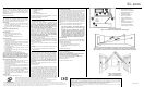
Figure 1: EL-2606 (cover off)/
Figure 1: EL-2606 (sans couvercle)/Figura 1: EL-2661 (sin tapa)
1. Antenna/Antenne/Antena
2. Battery Holder/Support de
Batterie/Soporte de la Batería
3. LED Indicator/Indicateur de
LED/Indicador LED
4. Terminal Block/Borniers/
Bloque de terminales
5. Tamper Switch/Contact
d’autoprotection/Llave del
Tamper
6. Mounting Knockouts/Trous de
fixation/Orificios Montaje
7. Acoustic Sensor/Détecteur
acoustique/Sensor Acústico
Figure 2: Acoustic Sensor Range Measurement (plate, tempered, laminated and wired glass)/
Figure 2: Mesures de portée du détecteur acoustique (verre de vitrine, tempéré, laminé et filaire)/
Figura 2:Rango de cobertura del sensor acústico (vidrio plano, templado, laminado y alambrado)
Figure 3: Testing the EL-2606/
Figure 3: Test du EL-2606/
Figura 3: Testeando el EL-2606