Summit 3208GLD Installation, Operation and Programming Electronics Line (E.L.) Ltd. www.elecline.com E L E C T R O N I C S L I N E ’ S T E C H N I C A L S U P P O R T D E P A R T M E N T : (972)-3-9211110 Electronics Line (E.L.) Ltd. reserves the right to change the information within this manual without prior notice.
TABLE OF CONTENTS Introduction..................................................................................................................................................3 About the Summit 3208GLD Installation, Operation and Programming Manual ................................................... 3 Publication Information ......................................................................................................................................... 3 Chapter One: Overview ......................
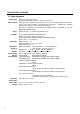
CHAPTER ONE: OVERVIEW 1.1: Specifications Power Input Power Output Zones Keypads User Codes Open/Close Windows Remote Programming Current Consumption Operating Temperature Dimensions Weight 4 AC: 15Vac, 30VA transformer. Battery backup: 12Vdc, 6.5 Ah or 7Ah (UL requirement). Auxiliary power - regulated 12Vdc nominal at 1A max. including keypads and detection devices for 4 hours standby. (For CSFM Fire applications - 220mA max. including keypads and smoke detectors for 24 hours standby).
1.2: Zones The Summit 3208GLD comprises 8 on-board zones that are expandable to a total of 32. Both hardwire and wireless zone expanders are available. Each zone can be precisely configured to suit a wide variety of applications. Zone Descriptors Each zone can be assigned an individual zone descriptor. These can be chosen from the standard zone descriptor library or from one of the four custom zone descriptors that are programmable by the installer.
System Partitioning The system can be partitioned into a maximum of 4 independent sub-systems with individual account numbers, keypads, user codes and relays assigned exclusively for each sub-system. A sub-system is created when at least one zone is assigned to it. 1.3: Telephone Dialer The Summit 3208GLD allows for up to four different telephone numbers to be programmed into the system using either pulse or tone dialing.
1.5: Other Features Opening and Closing Windows This feature helps cut down on the amount of opening and closing reports sent to the central station. The opening and closing windows are programmable windows of time, during which the user usually arms or disarms the system. Disarming during an opening window or arming during a closing window does not send a report to the central station.
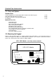
CHAPTER TWO: INSTALLATION 2.1: Parts and Options Standard Parts Summit 3208GLD Household Burglary Alarm Control Panel without keypad 2.
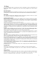
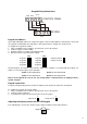
Keypad Wiring Connections LSCP GND VDD 5 6 - + 7 8 CONTROL PANEL WHITE GREEN RED BLACK KEYPAD GND - + VDD LSCP Keypad unit address Up to eight individually addressed supervised keypads can be installed with the control panel. If more than one keypad is installed with same unit address, all keypads must be configured as unsupervised. To configure the keypad unit address: 1. Using a small flat-head screwdriver, open the back cover of the keypad. 2. Locate the jumpers marked “CBA”. 3.
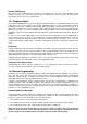
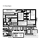
2.3: Wiring Diagram Electronics Line (E.L.) Ltd. For Future Use Long Range Radio Interface Connector SUMMIT 3208GLD Household Burglary and Fire Alarm Panel TELCOM 1 & 2: Outgoing line to telephone 3 & 4: Incoming line from telephone company Factory Test Point TELCOM 4 & 5: Incoming line from telephone company 3 & 6: Outgoing line to telephone J4 -or- 1 8 N.C. C. N.O. N.O.
2.4: Terminal Connections Telephone Connections Connector J4: The telephone line should be connected as follows: Incoming Line from Telephone Company 1 2 3 4 L+ L- Home Tip Outgoing Line to Telephone Outgoing Line to Telephone L+ L- Earth Home Ring -OrTelco Ring 1 Incoming Line from Telephone Company 2 3 4 5 6 7 8 8-Position Telephone Socket On-Board Relay Contacts Terminals 1, 2, 3 and 4: K5: 1 - N.C., 2 - Common, 3 - N.O. K6: 4 - N.O.
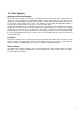
2.5: Fuse Replacement There are 3 protection fuses on the Summit 3208GLD control panel board, the layout of the fuses is shown in the following diagram: Battery Protection Fuse 3 Amp / 250V F1 Bell Power Output Protection Fuse 3 Amp / 250V F3 AUX Power Output Protection Fuse 1.6 Amp / 250V F2 F1 (Battery Protection Fuse): Protects the battery charger circuit and the control panel from a short circuit. To replace this fuse use a bel 5MF3 or other 3A/250V fuse.
CHAPTER THREE: SYSTEM OPERATION FOR THE 3106 LED AND 3108 LCD KEYPADS 3.1: General The Summit 3208GLD can be operated by using either the 3108 LCD or 3106 LED keypads. All the parameters can be programmed using either the LCD keypad or the Remote Programmer software. Refer to Chapter Four: Programming, page 23, for instructions relating to programming the system. 3.
Keys and Keypad Functions 0 - 9: The numeric keys are used to enter user codes, telephone numbers, to issue commands and for numeric programming. Q , #: These keys are used in programming the control panel. Pressing the Q key during the exit delay cancels the delay, immediately arming the system. On the LCD keypad, the Q key is used for scrolling back during operation and programming. The # key is used for entering hexadecimal digits (A - F) during programming.
Zone Status Display Zone status will only be displayed if detailed display is selected Zone 1, Bedroom, is open ZONE 1 OPEN BEDROOM ZONE 3 BYPASSED FRONT DOOR ZONE 4 TAMPER Zone 3, Front Door, has been bypassed Zone 4 has been tampered with Zone 4, bedroom, is in alarm ZONE 4 IN ALARM BEDROOM System Status Display AC power has been disconnected: SYSTEM AC LOSS Backup battery is low (under 10.
Menu Selections Using the LCD Keypad To make a menu selection from the menu: 1. Press MENU/NEXT; the main menu will be displayed and the selection pointed to by >. 2. Press MENU/NEXT to scroll through the menu items. Pressing “Q“scrolls backwards and pressing any numeric key displays that number’s associated menu item. To abort at any time, press AWAY. 3. Press SELECT to select the displayed menu item (indicated by the arrow). Certain menu items may require an authorized passcode.
Immediate Arming The system can be immediately armed, canceling the entry or exit delay for the arming period. To arm the system immediately: • Press Q during the exit delay; the delay is cancelled and the system is armed immediately. Note: Immediate arming disables both the exit and entry delays for the arming period. 3.6: User Codes Most operations executed from the control panel require a user code. Different user code authorization levels restrict certain functions to specific users.
Note: In the message to the central station, the control panel always indicates the system of the keypad from which the duress code was entered. User codes and system partitioning When the Summit 3208GLD is partitioned into several sub-systems, user codes can be associated either with a specific sub-system or with the entire system. Assigning a user code to only one system will default all operations to that system.
3.9: Event Log The event log records the last 100 events the system has undergone. The event log uses the FIFO (first in, first out) method. Once the log is full, the oldest event will automatically be erased. The event log can only be viewed with the LCD keypad. View Event Log To view the event log: 1. From the View/Log menu select View Log or press SELECT 6, 1. 2. Enter an authorized user code. 3. Scroll through the log by pressing the MENU/NEXT key.
3.11: Tests Walk Test The walk test allows detection devices to be tested without generating an alarm. To perform a walk test: 1. Press SELECT 4, 2, 1 or select Walk Test from the Test menu. 2. Test the control panel’s detection devices; an opened zone causes the keypad to beep. 3. To end the walk test, press AWAY. Walk test mode is automatically terminated after 4 minutes and 15 seconds. Note: During a walk test, an open zone will not create an alarm.
Bell Cancel The bell is automatically stopped when the system is disarmed. To stop the bell manually: 1. On the LCD keypad, press SELECT 4, 4; the panel prompts you to enter a user code. 2. Enter an authorized user code; the bell stops ringing immediately and the system sends a Bell Cancel event code to the central station. or 1. On the LED keypad, press SELECT 4, 4; the Program LED lights up. 2.
Latch Key When the latch key feature is activated (address 411), the MENU/NEXT key is used to acknowledge arrivals or departures from the system during opening or closing windows. If MENU/NEXT is not pressed after the user code is entered, a ‘Failed to Open’ or ‘Failed to Close’ event code is sent to the central station. Zone Chime A zone can be programmed to chime when opened. To program a zone to chime: 1. Press SELECT 3,3. 2. Enter an authorized user code. 3.
CHAPTER FOUR: PROGRAMMING 4.1: General The Summit 3208GLD control panel can be programmed using either the 3108 LCD keypad or the Remote Programmer, Electronics Line’s up/downloading software. For keypad operation refer to Chapter 3. For programming using the Remote Programmer refer to the instructions provided with the software. Contact your nearest Electronics Line office or agent to obtain a copy of the software. 4.2: Guide to Programming The control panel has 500 parameter addresses.
After entering parameter changes Parameter address Group ID ADDR: 000 ZONE 01 VAL=> 58 08 12 05 First digit blinking Upon entering a digit, the display automatically moves to the next digit. To move to the next digit without entering a modification, press MENU/NEXT. To move back to the previous digit, press Q. Entering Hex data Pressing # scrolls through the hexadecimal digits A, B, C, D, E and F. If the original digit is decimal (0-9), press # to change the digit to A.
ADDRESSES 000-127: ZONE PARAMETERS 000-003: Zone # 1 Parameters Each zone is individually defined in four parameter addresses. The following four addresses relate to zone 1 but the method of programming zones 2 - 32 is identical. 000 LCD Zone Descriptor and Entry Delay for Zone #1 Select a zone descriptor and entry delay for zone 1 from the table below. Entry delay options #1, #2 and #3 are set at addresses 382, 383 and 384, respectively. The four custom LCD messages can be programmed at addresses 412-475.
001 First Digit: Loop Speed, Pulse Count and Swinger Setting for zone # 1 The following table lists the options for the loop speed, pulse count and swinger setting. A slow loop response (150ms) should be entered for motion sensors and contacts. Enter a fast loop response (50ms) for shock sensors. The three optional pulse count settings can be programmed at addresses 385-387 and the swinger setting is programmed at address 388.
Second Digit: Listen-In, Event Code Transmission to the Central Station and Bell Activation Select the type of output for this zone in the event of an alarm.
ADDRESSES 128 – 131: SYSTEM PARAMETERS These addresses offer a number of options for each sub-system. The keypad tones (beeps) and one-key arming feature for each sub-system can be set at these addresses. Program only system 1 for unpartitioned systems. 128 First Digit: Keypad Arming/Disarming Tones for System #1 Each sub-system’s keypads can be programmed to beep during arming, disarming and during the entry delay. Select the keypad tones for system #1 from the table below.
ADDRESSES 132 – 139: KEYPAD PARAMETERS The following addresses offer options for the configuration of each keypad. 132 First Digit: Backlight and Buzzer Operation for Keypad # 1 Select the backlight and buzzer options from the following table.
ADDRESSES 180 - 195: ACCOUNT NUMBERS Account numbers are transmitted to the central station with the event code to identify the source of the event. Each system can be given a separate account number. If the system is not partitioned, only enter the account number for System 1. For partitioned systems, program account numbers for all subsystems. Account numbers are entered in four consecutive addresses.
address 197). Note: When using the Follow-me feature, Ack1 is received when the user presses 0, 9 or # on their telephone and Ack2 is not relevant.
ADDRESSES 198 - 201: COMMUNICATION PROTOCOLS Each of the four telephone numbers is associated with a telephone communication protocol programmable at these addresses. These can be defined according to the protocol used in communications with the central station and whether the message sent will be from either the zone or event oriented event code tables. Telephone #4 is usually associated with the “follow-me” feature, as it is the lowest priority telephone number and can be modified by the user.
The following are the addresses for zone oriented event code messages. For event oriented codes refer to addresses 262 - 295.
254 255 256 257 258 259 260 261 Event code for user initiated bell cutoff Event code for “E” button Event code for “F” button Event code for “P” button Event code for keypad emergency restore Event code for duress Event code for periodic test Note: This event code is reported with user code 0. Event code for system initialization ADDRESSES 262 - 295: EVENT ORIENTED EVENT CODE TABLE The following is a guide to programming event codes. • 00 - No message is sent for this event.
ADDRESSES 296-310: EVENT & MESSAGE ROUTING Event code messages can be routed in several ways. Each telephone number can be set as a primary, back-up or duplicate number for a specific group of events. The control panel can also be programmed not to dial a certain telephone number for certain events. A primary number is the first number the control panel dials when an event occurs. If the control panel is unsuccessful in dialing the primary number, the back-up number is dialed.
299-301 Message routing for LSCP unit trouble messages Same as addresses 296 – 298 302-304 Message routings for fire trouble messages Same as addresses 296 - 298 Note: Fire zones have a fixed bell pattern - pulse on and off for half a second in groups of three with an interval of one and a half seconds between each sequence. The cut-off time is fixed at four minutes.
ADDRESS 388: SWINGER PARAMETERS Swinger mode. Defining a zone as a Swinger limits the number of alarms that can be generated from that zone within a pre-programmed amount of time. Each zone can be programmed with its Swinger option active. All swinger zones are assigned the same swinger setting. Example: If zone 1 is set as a swinger at address 001, and swinger mode is set to “1 alarm in 1 arming period” at address 388, only one alarm will be accepted from this zone within every one arming period.
396-409 Daily Windows Settings A different combination of windows can be programmed for each day of the week and for each system. Select a value for each digit of these addresses from the following table.
ADDRESSES 412-475: CUSTOM LCD ZONE DESCRIPTORS Four of the descriptors that can be assigned to each zone (see Address 000) can be customized to suit a specific installation. A total of sixteen characters, including spaces, can be entered for each LCD custom zone descriptor using the following table. Each custom zone descriptor is entered in a series of consecutive addresses. It is recommended to fill in all 16 characters for each custom zone descriptor.
ADDRESSES 477-490: RELAY PARAMETERS Output relay modules are optional add-on peripherals that are connected to the control panel via the LSCP bus. Relays can be used for various purposes including status indication, additional bell outputs and access control. Each individual relay is programmed at two addresses. 477 Operation Mode Relay 1(and onboard relay K5) Each relay can be programmed to activate or deactivate based on specific events or status conditions.
478 Output and Cutoff Relay 1(and onboard relay K5) The second address concerns the following characteristics of the relay’s operation.
492 Periodic Test Time Setting (Hour) The periodic test time is set at two addresses, 492 and 493. The hour at which the test will take place is programmed at this address. Note: If either the 6-hour or 12-hour test has been programmed this is the time of the first test. If the 1-hour test has been programmed, only the minutes setting needs to be defined (Address 493).
495 First Digit: Detailed Display The keypad can be programmed to show the detailed display at all times or only when the system is disarmed. First digit value: 0 – Detailed display only when system disarmed. 1 – Detailed display at all times. Second Digit: Fire Sensor Reset and Bell Muting for Listen-In Applications The second digit of this address concerns the following: • Power reset for latching smoke detectors – an activated fire sensor can be reset in two ways.
ADDRESSES 497-498: AC LOSS & RESTORE 497 AC loss report delay. The AC loss report delay determines how many minutes the panel will wait after AC power has been lost before transmitting a message to the central station. Select a value in hexadecimal for the AC loss report delay. For hexadecimal value conversions refer to the hexadecimal conversion chart located in Appendix B. 498 AC restore report delay.
APPENDIX A: TROUBLESHOOTING The following is a guide to troubleshooting, using the Summit 3208GLD security system. Problem Telephone line failure appears when the telephone line is not connected (control panel used as a local alarm). Reason Event codes programmed at values above “00”. Action Program event codes as “00” and power down the panel. Keypad display not responsive. A Keypad at a different address has been activated. Wait for time out to activate, or press “AWAY” key. No display on keypad.
APPENDIX B: HEXADECIMAL CONVERSION CHART The following is a decimal (i.e. number of hours, minutes, etc.
GLOSSARY 24 hr zone A zone which is always active regardless of whether the system is armed or disarmed. Opening a 24hr zone always generates an alarm. -AAC Loss Account Number Answering Machine Override Armed Arming Ring Audible Alarm Authorization Level Auto Arming The disruption of AC power. The number transmitted to the central station along with an event code to identify the source of the event.
Communication Protocol Conditional Zone See Protocol. A zone that will not generate an alarm during the entry delay. -DDealer Lockout Default Program Detailed Display Disarmed Distress Keys Duplicate Number Duress Code An option that disables the default restore code “123456”. The default program contains the factory parameter settings. For typical installations, the default program minimizes the amount of programming that needs to be performed by the installer.
-LLatch Key Late to Close A feature designed to inform parents whether their children have arrived home safely. The panel sends a message to the central station and/or the follow-me number if MENU/NEXT is not pressed during the appropriate window. A command that extends the closing window period if the system needs to be armed later than usual – see Closing Window. -MManual Programming MENU/NEXT key Message Routing Programming from either a LCD or LED keypad.
Summarized Display Supervised Keypad Swinger Zone A keypad display mode without zone status – see Detailed Display. A supervised keypad generates an alarm when disconnected from the control panel. A zone from which the number of alarms sent within a predetermined time period is limited. -TTelephone Communicator Test Toll Saver Transistor Module Trouble Tones A manual test that checks the control panel’s ability to communicate with all programmed telephone numbers. See Callback.
ELECTRONICS LINE (E. L.) LTD. AND ITS SUBSIDIARIES - LIMITED WARRANTY ELECTRONICS LINE (E. L.) LTD. AND ITS SUBSIDIARIES (EL) warrants its products to be free from manufacturing defects in materials and workmanship for two years following the date of sale. EL will, within said period, at its option, repair or replace any product failing to operate correctly without charge to the original purchaser or user. In case of defect, contact the security professional who installed and maintains your security system.