Operations Manual and Users Guide BIJOU Ver. 2.11 1675 NW Cornelius Pass RD Hillsboro, OR 97124 USA 503.645.5533 800.547.2690 FAX 503.629.
ABOUT THE MANUAL 5 ABOUT THE BIJOU 5 SECTION I: SYSTEM DETAILS AND ASSEMBLY FOR OPERATION (THE BORING STUFF) 6 REAR PANEL OF THE CONTROL CONSOLE ....................................... ....................................... 7 ASSEMBLY ................................................................ ............................................................................................. ............................................................. 8 FRONT PANEL ................................
Table of Figures Figure 1 Bijou .........................................................................................................5 figure 2 Bijou Rear Panel........................................................................................7 Figure 3 Front Panel...............................................................................................9 Figure 4 Screen Keys ...........................................................................................10 Figure 5 Action Keys...
ABOUT THE MANUAL This manual (like most operations manuals) is divided into Sections and Chapters. The first section is the boring section and contains all of the details about what all the “PARTS” are. Unfortunately, if you are new to lighting control and do not learn the parts, their locations and functions you will not be able to do the interesting stuff like cues and effects.
SECTION I: SYSTEM DETAILS AND ASSEMBLY FOR OPERATION (The boring stuff) To operate your new Bijou carefully open the packing/shipping boxes and locate the following: 1. 2. 3. 4. 5. 6. Control console Universal Power Pack/power cord (may be 2 pieces) Alpha Numeric key board (optional) VGA/SVGA display (may be owner provided) DMX cable (optional) Computer disk/s (PC format, 3.
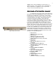
NOTES: Dust, smoke and liquids can ruin any piece of quality electronics. Keep operation areas clean and do not allow contamination of equipment. Do not operate this console in a wet environment (the rain). REAR PANEL OF THE CONTROL CONSOLE figure 2 Bijou Rear Panel Located on the rear of the console are the output and input jacks, power jack and On/Off power switch. Refer to the key below for an explanation of each item.
ASSEMBLY Refer to REAR PANEL for location of appropriate jacks/plugs for assembly prior to start. To assemble the Bijou for operation: First (with the ‘On/Off’ switch in the off position) plug in the Universal Power Pack/cord into the ‘Power Input’ jack on the back of the Bijou. Next plug the parallel blade U-Ground end into a ‘Surge protected’, outlet. Like all microprocessor-based controls, the Bijou is sensitive to power fluctuations on standard power lines.
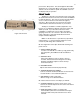
push it to the ‘On’ position. This should light two blue LED’s dotting the ‘I & J’ in the name Bijou on the front of the console and the console should boot up with the “STAGE” screen on the display ready for operation. FRONT PANEL The Bijou is a microprocessor-based control system with all operational instruction sets and control routines embedded in read-only memory. The control console front panel allows access to these instructions and routines through key selections.
CONTROL KEYS The primary access to the control system is through the keypad controls on the front panel of the console. The keypads are grouped together under common control headings for ease of operation. There are four groups of keys. 1. 2. 3. 4. Screen Keys Action Keys Number Keys XY & AB Fade Control Keys SCREEN KEYS The Screen Keys access the primary displays of the control console. The control console display screen can be changed at any point by selecting a different Screen Key.
action) operation. PATCH [Patch Profile] (first hit) This screen shows the system patch tables by dimmer. Dimmers can be assigned to channels with proportional levels and profiles. Dimmers may also be "Parked” at a level, bypassing both the grand master and the black out switch.
[Page Up] Used to change position of display screen to see the last major full screen block of information. [Page Down] Used to change position of display to see the next major full screen block of information. [FI], [F2], [F3] The three ‘F’ (function) keys are “soft” keys. By this we mean that their function changes for each screen. Function keys are defined by their use in the lower right corner of each individual screen, color code is magenta.
NUMBER KEYS NUMBER KEY PAD Number keys are the primary way to enter values into the Cues, Times, Submasters and Effects, Number Keys are always reflected on the system Command Line (lower left of screen). NUMBER KEYS [1] thru [0] Make a selection by entering the value on the Command Line. DECIMAL KEY [.] Used to insert additional steps between whole number cues or to identify tenth of seconds in timing operations. FL Key [FL] Also called FULL, assigns a value of 100% to a level in a command sequence.
MAIN MENU The Setup Screen is divided into two columns. The left column lists the topics that may be addressed and the right column lists the items that may be modified, configured or actions that can be taken under that topic. By using the [Next] and [Last] keys you step thru the seven setup topics. Note that as you step thru the column the green headings will change to light blue indicating the active category.
in the previous cue the level for that channel will “track” thru and into the cue you are creating. In a Preset Cue only those channels with levels set will have a level no matter what the previous cue had recorded for the channels.) 6. Record Subs in Cue A ‘Yes’ means that if a Submaster is active, it’s output (live on stage) will be recorded as part of any cue or submaster you record well in the stage screen.
2. Update AB Fader A “Yes’ assumes that you are creating memory cues and recording them on the AB cross faders. And that you want to use the [Update] key to confirm and store any modifications that you make to an existing cue. This would be the normal mode of operation if you plan to use the board in either 2 scene or 1 scene manual operation simultaneously with memory mode operation.
7. Restores original factory default settings without clearing Cues, Effects, Submasters etc. 8. Restores all 25 dimmer Profiles to the original default settings. 9. Clears all user-recorded information from the system memory. SAVE TO DISK The Save to Disk menu is used to transfer any recorded information from the console to the disk for off-line storage.
PRINT FUNCTIONS The Print Functions menu allows access to all print features. Item: 1. Allows you to print only the channel output levels for each cue. 2. Print extra line. Some printers require this command to advance the paper at the end of each line of print. Use YES command if your printer is over printing and not advancing. 3 - 7. Prints all information for; cues, subs, effects, macros and patch.
activates input/output port and screen for programming MIDI activated events. If the clock is not set to the proper time you should set it at this time. The time will stay accurate even with the power turned off as the board has a battery backup built in to protect memory loss. SECTION II: BIJOU OPERATIONS the fun stuff. Figure 16 Bijou disk drive O.K. we are going to actually start operating the machine rather than just looking at it.
information from the system and allow you to start operating the machine with a clean slate. PATCH (screen) To begin you need to understand what a patch is. In a lighting system you will have many lighting fixtures that you “plug” into dimmer circuits. You may have several light fixtures “plugged” into a single dimmer circuit because they are being used together and do not need individual control.
The default Profile is 1, if you do not enter a profile for a dimmer the system assumes Profile 1 and leaves the PRF row (brown) empty. By leaving the LEV (white) and PRF (brown) rows empty it is easier to find those dimmers where you have specifically modified the output of the dimmer. If you wanted to do the same thing but give the dimmer a maximum output of 80% the keystrokes would be; [3] [At] [1] [At] [8] [0] [Enter].
NON-DIM Dimmers can be patched and operated as a Non-Dim. A Non-Dim goes from 0 to 100% instantly. It is your On/Off switch for circuits that can not be dimmed. You may use a Non-Dim to turn on a fog machine, mirror ball, prop radio or TV. To assign a dimmer as a Non-Dim you need to select the DMR and assign it to a CHN then you hit the [At] [.] followed by a LEV. The LEV in this case is the position in the fade where the Non-Dim turns On or Off.
output of the dimmer equal to the percentage of travel of the fader. So if you raise a channel fader to a level of 65 the dimmer will be at 65% of its total output. If you do not select a different profile for a dimmer when you create your patch screen the Bijou will automatically assign Profile 1 to the dimmer. Figure 19 Profile Screen You will see on the PROFILE screen Profiles 2, 3 & 4 listed as Preheat.
Screen you will see that the change you made to Profile 17 has been cleared. NOTE: All 25 profiles may be modified by the operator to suit your needs but it is suggested that you leave Profiles 1 7 at their factory defaults to avoid confusing other operators who may not know that the dimmer is not ‘ghosting’ it has been given a hot preheat.
HELP Figure 21 Help Window The HELP section is designed to assist the operator by letting them know what keystrokes are logical for the present operation. This screen is a dynamic screen that will change as you input data to reflect the next keystroke choices. So if we were to enter a channel # the screen will change to tell the operator that the next logical keys would be And, Thru, Except or At.
GRANDMASTER In order for levels you are setting to be seen on stage, the Blackout switch needs to be off (LED off) and the Grandmaster faded to its full on position. The Grandmaster is in proportional control of all Channel/fader outputs from the control console except ‘Parked’ dimmers. It can be used to do fade to black cues for set changes and blackouts for end of scenes. At this time fade the Grandmaster to its full on position.
If you are going to do the cross fade in time the operator should be given a WARNING CUE #, then a READY CUE # ON A 3 COUNT and finally a CUE # ON A 3 COUNT…GO. The operator would then count back in time as the cross fader is moved; 3 (on the go) one thousand, 2 one thousand, 1 one thousand, COMPLETE. Now that the XY cross fader is in the up or X position you can set the next set of Channel/fader levels for the next cue on the bottom Y row of faders.
Another use of both 2 Scene, but more often 1 Scene, is to manually establish a lighting look on stage and then record that look to a memory preset. The use of this function will be covered in a latter section covering memory operations. Be aware that both 2 Scene and 1 Scene operation can be used independent of memory operation or in conjunction with memory operation. The choice is up to the operator based on the needs of the production. This makes the Bijou an extremely flexible control console.
faded up to full as well. In most cases well operating in 1 Scene mode you do not set a cue up, go into it, fade it out, set another cue, fade into it, fade out, set the next, fade in, fade out, set, in, out, set, etc.. In most uses of 1 Scene operation once the initial look is set it is then modified by moving individual Channel/faders, one at a time or in groups, dependent on the number of fingers you use to move them.
position and the XY fader is in the Up (near [Load] & [Fade Take]). RECORDING A CUE FROM LEVELS SET WITH THE CHANNEL FADERS: To record your first cue/preset, push Channel/faders 110 up to a level of 10 or 100%. To record this to a cue all you need to do is press [Record] the command line will state ‘”RECORD CUE” then input a cue # so press [1] followed by [Enter]. You could than repeat this operation over and over with different Channel/fader levels and cue #’ until you have a show you like.
Figure 25 Cue List Screen TIMED FADES Notice that in the TIME window of the screen for AB it says MAN or manual. This means that you can not fade the cue in using the [Go] button. So now using the AB cross fader fade Cue 1 to 0% or off. Press [Load] [Enter] which clears (unloads) the AB cross fader. Now to run the cue with the default 5 count you saw on the CUE LIST screen press the [Fade Take] key above the B fader. This removes the MAN (manual) operation from the AB Cross faders.
second fade. If you were to stop here and ended the command with [Enter] Cue 2 would be recorded with an Up TIME of 3 seconds and a Down TIME of 3 seconds. But lets make the cue more complex by making the down time an 8 count. So your next keystroke is [Time] and now you will see the command line reads; RECORD CUE 2 TIME (UP/DOWN ARROW) 3 TIME (DOWN ARROW). This signifies that the next # you input will be the Fade Down time so press [8] [Enter].
the STAGE Screen with only Channel 26 at a level of FL. To set channel levels via the keypad you start by entering the channel and or channels you wish to address. This can be one channel at a time such as; [1] [At] [Fl] [Enter]. Note that now on your STAGE Screen you will see Channel 1 (yellow indicating it is the channel/channels addressed) at FL with level now in brown (not white). The brown tells you that the level has been entered manually (via the keypad) and has not been recorded to a cue.
line read ‘ALL AT’ then press [At] [0] [Enter]. If you wish to set them all to a level other than 0% just insert a level after the [At] key and all 512 channels will go to the new level. [Enter] [At] can also be used with the Encoder wheel to adjust the overall level of a cue. Or you can use this function to set all of the channels to the same level.
Channel/faders down to 0% at the end of a cue, you only change the Channel/faders that are going to a new level in the next cue and leaving the others alone. So some levels “track” through the reset of the cue. If you wish the Bijou to be a Tracking board all of the time you can change to this mode as the default in the SETUP Screen.
Now return to STAGE Screen and [Load] cue [4] to the AB cross fader and press [Go] to fade into it. Now you will see Cue 5 loaded and ready to fade into. But you will also see a new set of dialog to the left of the help screen. This should say: ABPARTS LEVCUE 6 7 8 9 This shows that the you have a multipart cue ready to run. And as soon as you press the go all of the cues that are part of the set will begin. The LEV column will indicate the progression of the fade in.
run thru the your cues without them. If the next night you find that the broken toe was only a sprain and the dance number is back in you can clear the link by going to the CUE LIST screen then change the Link for Cue 33 to [F2] [0] [Enter]. Putting a ‘0’ in the Link column clears it. Now you can run all 100 cues in order. LOAD Cue or GO TO CUE The [Load] key can be used as a Go-To-Cue key.
One good use of this ability is running the basic show cues (say Cues 0.5 thru 300) on the AB cross fader. And at the same time using the XY cross fader to run the cues for the sunrise thru sunset thru night cues on the cyclorama using Cues 500 - 550. Or you might want to use one set of cross faders for control of color changers leaving the other cross fader for lighting cues only.
MODIFIYING AN EXISTING CUES ATTRIBUTES CUE PREVIEW SCREEN In this screen you do not have to use the strict sequence of keystrokes that you used in the STAGE screen to enter times or types. The CUE PREVIEW screen always opens to the same cue that is live onstage (STAGE screen). To change to a different cue you can press [Cue] followed by the cue number [#] [Enter] or you can use the [Next] [Last] keys to sequence thru all of the cues you have written.
be access by using the [Page Down] [Page Up] and [Next] [Last] keys or by pressing [Cue] [#] [Enter] which will jump you directly to the desired cue. Once you have accessed the desired cue the cue Type can be changed by using the [F3] [Enter] keys. Channel numbers appear in blue across the top of the screen with the channel output level listed below it for each cue. Channel output levels are shown in either white or gray.
Submaster window and on the console Submaster LED’s. On the stage screen the submasters are shown on the bottom of the screen as: E/Pg: = Effect Number if in yellow and submaster page if in green. Sub: Handle numbers 01 02 03 04……………..24 Lev:= submaster output level.
keyboard to enter a name for the desired Submaster when working/viewing it on the SUB PREVIEW screen. So type for your new Submaster Pg 1 Sub 1 type in the name Work Lights. Now press [Sub-master/List] twice to return to the SUB LIST screen and you will see that the name has been entered here as well. So now we have one submaster recorded and we need to record a second on Pg (page) 2. To do this press [F2] [2] [Enter].
green as active. You will also see that Sub: 02 has a page number (Pg: 2) above it. RECORDING SUBMASTERS FROM THE STAGE SCREEN As you are now on the stage screen load a Cue onto the AB Crossfader and fade into it. (If you had read the manual from the beginning you would know how to do this.) Now add in a few of the manual faders from the 1 Scene/2 Scene XY Crossfader.
INHB= Inhibitive mode, think of this as a “Reverse Fader”. In operation as you raise the inhibitive fader from 0 to 10 the lighting channels associated with that Submaster go down not up. This can be handy when you have a fixture that goes out of focus (who forgot to tighten the lock down handle?) and you do not want to rewrite every cue in the middle of the show. Instead you could record that channel to a Submaster at [Fl] then make that Submasters Type = INHB.
screen and press Pg: 1 Sub:1 bump button. The levels will fade up and stay on until you press the bump button again to start the fade out. MERGING A SUBMASTER INTO A CUE As stated at the beginning of this section a Submaster is a ‘Group’ of channels that are controllable from one fader/handle. Many times you can speed the cue recording process by calling up a ‘Group’ at a level rather than all of the individual channels separately.
editing on this page it is a read only screen. EFFECTS Effects are sequential, automated lighting changes. They can be as simple as a repeated On/Off or so complex that they involve all 512 channels of dimmers that the Bijou controls. CREATING AN EFFECT The EFFECT screen [Effect/Macro] is used to create an effect. In the lower right of the screen you will see the Effect # which should be 1 if you are just learning the board.
the same time move all of the remaining steps down one step and renumber them sequentially for you. To delete a step you press [Delete] [F2] followed by the step number [#] you wish to delete. The command line at the lower left of the screen will read DELETE STEP #. To complete the action press [Enter]. This will delete the desired step, move up all subsequent steps and renumber them for you. EFFECT TYPES The effect you have created has a default operations mode of Forward.
This will load a yellow 01 on the E/Pg: line directly above a yellow 24 on the Sub: line of the Submaster control section of the STAGE screen. Any yellow numbers in this section indicates that an effect has been loaded to operate with that Submaster. To run the effect you can fade it up at any rate you wish using the Submaster fader or you can turn it on instantly using the Submasters bump button. (The instant on bump button option is best when using a Single Mode Effect as lightening.
TO RUN A MACRO To run a macro, from any screen, press [Macro #] followed by the number of the macro you want to run [1] then [Enter] which makes the macro run. To run the macro you just created press [Macro#] [1] [Enter] which will take you to the SETUP screen, Save To Disk, 8. SAVE ALL, Are you sure? Command. Now all you have to do before you take a break is press [Enter] and you will have saved all of your work to disk. Another good use for macros is to change the active patch between acts.
REMOTE VIDEO The console can be fitted to output the Super VGA signal to remote locations. (Distances greater than 25 feet) When fitted with this option, the 4-pin XLR connector will output the signal. When installed with a system, a remote video receiver is required to interface to a standard SVGA monitor.
DESIGNER’S REMOTE The Bijou Consoles support a Designer’s Remote console which offers duplicate keypad features remote from the control console. Coupled with the Bijou’s remote capacity, the Designer’s Remote offers the features of the console with interactive video support. The Designer’s remote is supplied with a 4-pin XLR connector on the rear output plate. Connect this 4-pin XLR to a mated connector on a receptacle plate or on the back of the console.