VERSION 0.
REVISIONS Revision Author Date Changes 0.1 J. Walz September 29, 2020 Initial Draft 0.2 J. Walz November 13, 2020 Added FCC Compliance Statement 0.3 J. Walz November 24, 2020 Updated Safety and Specifications 0.4 J. Walz December 1, 2020 Updated Battery Temperature Profile 0.5 J. Walz December 18, 2020 Added Current Profile 0.6 J.
TABLE OF CONTENTS Revisions ................................................................................................................................................... 1 Abbreviation.............................................................................................................................................. 1 FCC Compliance and Advisory Statement .................................................................................................
Transducer Connections ...................................................................................................................... 18 Ratings ................................................................................................................................................. 18 Specifications .......................................................................................................................................... 19 Operating Current Profile ...........................
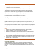
FCC COMPLIANCE AND ADVISORY STATEMENT This device complies with Part 15 of the FCC rules. Operation is subject to the following two conditions: 1. This device may not cause harmful interference. 2. This device must accept any interference received, including interference that may cause undesired operation. This equipment has been tested and found to comply with the limits for a Class A digital device, pursuant to part 15 of the FCC Rules.
INTENDED USE The BMS-1001-TH is intended to be installed and operated in an indoor industrial environment only. The wireless system is Class A equipment and may cause radio interference in residential areas. Only authorized, trained personnel are permitted to possess, install, and operate the BMS-1001-TH. The device should be installed only in locations where the general public has restricted access. The BMS-1001-TH is sold directly to electric utility companies by Electronics4All Inc.
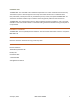
BMS-1001-TH BATTERY MONITORING SYSTEM The BMS-1001-TH Battery Monitoring System (BMS) is designed to monitor the individual voltages of series-connected battery cells. The system is targeted towards lead-acid battery banks used for electric power plant generator start-up. Each BMS can monitor between 7 and 10 cells, and may be ganged to monitor up to 96 cells. Each BMS supports the connection of a halleffect current transducer to monitor battery string current.
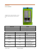
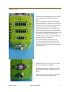
INTERFACES FRONT MEMBRANE The BMS contains 3 tactile push buttons, 2 rotary encoders, and 8 status LEDs on the front of the unit.
Bat Low Red Fault Red interface Indicates that the internal lithium-ion battery charge is low. The AC/DC adapter or USB should be connected to recharge the battery. Current firmware (Rev. 3111) turns on the LED when less than 500 mAh is remaining, and turns off the LED when the charge exceeds 1000 mAh Turns on when a fault is detected.
CONNECTIONS NC 10 9 8 7 6 The external lead-acid battery bank is connected to the screw terminals on the bottom of the BMS. Each cell voltage input supports measurement range of 0-5 VDC. Up to 10 series connected cells may be monitored. The maximum input range of the entire string must not exceed 36 VDC.
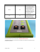
BATTERY BANK WIRING TERMINAL PLUG The 6-pin battery cell input terminal receptacles are designed to mate with Phoenix Contact Terminal Block Plug 1827745. WIRE CONNECTIONS Ferrules required on all wire input connections to prevent loose wire strands from contacting adjacent terminals. The Phoenix Contact 1827745 terminal plug accepts the following: Connection Type Ferrule Tip Cross Section Conductor cross section flexible, with ferrule without plastic sleeve 0.25 mm2 to 1.
LEFT PIN 6 PIN 5 TOP OF STACK OR NEXT BATTERY BANK NOT USED CELL 10 DPST DISCONNECT 0 - 5.00 VDC PIN 4 J1: UPPER CONNECTOR PIN 3 CELL 9 0 - 5.00 VDC CELL 8 0 - 5.00 VDC PIN 2 CELL 7 0 - 5.00 VDC RIGHT PIN 1 CELL 6 0 - 5.00 VDC LEFT PIN 6 11.00 VDC MINIMUM 36.00 VDC MAXIMUM CELL 5 0 - 5.00 VDC PIN 5 CELL 4 0 - 5.00 VDC PIN 4 J2: LOWER CONNECTOR PIN 3 CELL 3 0 - 5.00 VDC CELL 2 0 - 5.00 VDC PIN 2 CELL 1 0 - 5.
SYSTEM CONNECTION ARRANGEMENT A site analysis should be performed when deploying a BMS system to ensure that all cells within a battery bank are adequately monitored, and the input rating of each individual BMS is not exceed. For example, the typical lead-acid battery bank used for generator start-up is comprised of 96 seriesconnected cells with a nominal float voltage of 2.70 VDC and an absolute minimum (discharged) voltage of 1.80 VDC. To monitor the entire battery system, 10 BMS' are required: 1.
LEFT PIN 6 TOP OF STACK OR NEXT BATTERY BANK NOT USED CELL 10 PIN 5 PIN 5 PIN 4 CELL 8 PIN 3 PIN 6 PIN 3 CELL 7 PIN 2 LEFT PIN 2 CELL 6 RIGHT PIN 1 LEFT PIN 6 CELL 5 CELL 4 PIN 5 PIN 5 CELL 3 PIN 4 PIN 4 J2: LOWER CONNECTOR CELL 10 CELL 9 DPST DISCONNECT CELL 8 CELL 7 CELL 6 CELL 5 CELL 4 CELL 3 J2: LOWER CONNECTOR CELL 2 PIN 3 PIN 3 CELL 1 PIN 2 RIGHT TOP OF STACK OR NEXT BATTERY BANK NOT USED J1: UPPER CONNECTOR J1: UPPER CONNECTOR PIN 1 PIN 6 DPST DISCONN
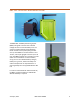
MOUNTING BRACKET A mounting bracket is provided on the rear of the BMS that connects to a standard 35 mm DIN rail. ANTENNA The BMS-1001-TH is designed to operate with the following antenna: Manufacturer: Part Number: Frequency: Gain: Nominal Impedance: VSWR: Polarization: Electrical Length: Radiation: January 8, 2021 PulseLarsen Antennas W1010 2.4 – 2.5 GHz 2.0 dBi 50 Ω ≤ 2.
PAIRING PAIRING STATUS To determine if the BMS has been paired with a Gateway, press and release the PB1 pushbutton. If the green COM LED turns on for 1 second, the BMS is paired with a Gateway. If the red COM LED turns on for 1 second, the BMS is not paired with a Gateway. PAIRING A BMS TO A GATEWAY 1. Place the target Gateway in Pairing Mode by pressing and releasing the PB1 pushbutton on the Gateway. The green COM LED will turn on. 2. Press and hold the PB1 button on the BMS.
INTERNAL BATTERY A 3300 mAh lithium-ion battery is installed in the BMS to provide reserve power should a fault occur with external lead-acid battery bank. The internal battery provides power to the external interfaces, the Bluetooth link, and the current transducer circuitry. When the BMS is drawing power from the internal battery, the green 'Li-Ion' LED on the front membrane will be on. The BMS will operate for approximately 11 days from a fully-charged internal battery and a 30 second broadcast rate.
The BMS will disable all operation once battery temperature exceeds 60 °C. Discharge operation will resume once the temperature drops below 55 °C. NOTE: The BMS should not be shipped with the internal battery installed. When transporting a BMS, the lithium-ion battery should be removed and shipped separately using an approved UN/DOT 38.3 shipping container. RESET The BMS may be reset at any time by pressing and holding both the PB1 and PB2 buttons for at least 4 seconds.
WIRE CONNECTIONS Ferrules are required on all wire input connections to prevent loose wire strands from contacting adjacent terminals. The Phoenix Contact 1827729 terminal plug accepts the following: Connection Type Ferrule Tip Cross Section Conductor cross section flexible, with ferrule without plastic sleeve 0.25 mm2 to 1.5 mm2 Conductor cross section flexible, with ferrule with plastic sleeve 0.25 mm2 to 0.
SPECIFICATIONS Aspect Description Power Overvoltage Category 1 Supply Voltage (DC Input) 7.00 DC to 15.00 VDC (2.5 × 5.5 mm Barrel Jack) Supply Current (DC Input) 1.50 A @ 12.00 VDC, 25 °C Ambient (Internal Battery Charging) Supply Voltage (Lead-Acid) 11.00 to 36.00 VDC (External Lead-Acid Battery String) Supply Current (Lead-Acid) 9.9 mA (ON), 6.3 mA (OFF) @ 25.00 VDC, 25 °C Ambient Battery Manufacturer Panasonic Part Number NCR18650B Rated Capacity 3400 mAh Nominal Voltage 3.
Radio Wireless Processor Security • • • • 48 MHz Arm Cortex M4F Processor 2.4-GHz RF Transceiver Compatible with BLE 5.
FCC 2AXVKBMS01 Industry Canada 26661-BMS01 Safety 61010-1 Accessories Internal Battery Panasonic NCR18650B 3400 mAh 3.6V Antenna PulseLarsen Antennas W1010 AC/DC Adapter CUI Inc. SWI24-12-N-P6 Current Transducer CR Magnetics CR5210-50 Mating Connectors Battery Cells (6 Pin): Phoenix Contact 1827745 Current Transducer (4 Pin): Phoenix Contact 1827729 OPERATING CURRENT PROFILE 16.00 14.00 Current (mA) 12.00 10.00 8.00 ON Current 6.00 OFF Current 4.00 2.00 0.