VERSION 0.
REVISIONS Revision Author Date Changes 0.1 J. Walz September 29, 2020 Initial Draft 0.2 J. Walz November 13, 2020 Added FCC Compliance Statement 0.3 J. Walz November 23, 2020 Updated Safety and Specifications 0.4 J. Walz December 2, 2020 Modified IC Compliance Statement 0.5 J.
TABLE OF CONTENTS Revisions ................................................................................................................................................... 1 Abbreviations ............................................................................................................................................ 1 FCC Compliance and Advisory Statement .................................................................................................
Specifications ..........................................................................................................................................
FCC COMPLIANCE AND ADVISORY STATEMENT This device complies with Part 15 of the FCC rules. Operation is subject to the following two conditions: 1. This device may not cause harmful interference. 2. This device must accept any interference received, including interference that may cause undesired operation. This equipment has been tested and found to comply with the limits for a Class A digital device, pursuant to part 15 of the FCC Rules.
INTENDED USE The GTW-BL100 is intended to be installed and operated in an indoor industrial environment only. The wireless system is Class A equipment and may cause radio interference in residential areas. Only authorized, trained personnel are permitted to possess, install, and operate the GTW-BL100. The device should be installed only in locations where the general public has restricted access. The GTW-BL100 is sold directly to electric utility companies by Electronics4All Inc.
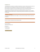
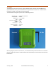
GTW-BL100 WIRELESS GATEWAY The GTW-BL100 Wireless Gateway is designed to receive encrypted data packets from compatible Bluetooth enabled industrial sensors and to route the data to a MQTT Broker over Ethernet. COMPATIBLE SENSORS Description Model Number BMS 4-20mA Current Loop Receiver Wireless Thermocouple BMS-1001-TH TBD TBD INTERFACES The Gateway contains 3 tactile push buttons and 4 status LEDs on the top of the unit.
COM (RIGHT) Green Fault Red pairing and reception of data Used to indicate status of BLE pairing and reception of data Blinks every 2 seconds when a fault is detected with either the Ethernet connection or connection to the MQTT Broker. The specific fault will be displayed on the serial terminal. Automatically clears when the fault is removed. CONNECTIONS DC Input Ethernet USB DC INPUT The DC input accepts a 2.5 mm x 5.5 mm barrel plug.
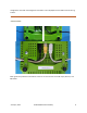
configuration. Note that some diagnostic information is also displayed over the USB connection during runtime. HARDWARE CABLE GUIDES Cable guides are provided on the bottom of the unit to route and secure the DC input, Ethernet, and USB cables.
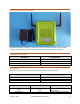
ANTENNA The Gateway has two antenna ports to support different wireless protocols. The GTW-BL100 only supports Bluetooth, so only the 2.4 GHz antenna is required to be connected. The 2.4 GHz antenna connection is located on the right front of the Gateway. The GTW-BL100 is designed to operate with the following antenna: Manufacturer: Part Number: Frequency: Gain: Nominal Impedance: VSWR: Polarization: Electrical Length: Radiation: PulseLarsen Antennas W1010 2.4 – 2.5 GHz 2.0 dBi 50 Ω ≤ 2.
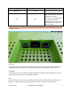
MOUNTING BRACKET A mounting bracket is supplied that may be used to mount the Gateway to a wall or other support structure. The mounting bracket slots support 10-32 screw heads. To secure the mounting bracket to the Gateway, remove the four (4) rubber feet and screw the bracket to the enclosure using two (2) 8-32 × ½" screws.
DEPLOYMENT 1. Program the Gateway (Node) ID and MQTT Broker IP address into the Gateway. 2. Connect the 2.4 GHz antenna to the Gateway. 3. Plug the DC input power to the Gateway. The gateway defaults to power ON. The orange PWR LED will turn ON, and the red Fault LED will start to blink at 2 second intervals. You may also see the red COM LED flash at 5 second intervals. 4. Plug in the Ethernet cable.
PAIRING These instructions for pairing a Bluetooth sensor to the Gateway should be used in conjunction with the instructions included with the Bluetooth sensor. 1. Place the Gateway in Pairing Mode by pressing and releasing the PB1 pushbutton on the Gateway. The green COM LED will turn on. 2. Follow the instructions for the target Bluetooth sensor to place it in Pairing Mode. 3. If pairing was successful, the green COM LED on the Gateway will turn off.
GATEWAY CONFIGURATION The Gateway ID and MQTT Broker IP are set via a USB interface to a PC. A serial terminal program (e.g. Tera Term, Hercules) is required. Download links are provided below. Tera Term: https://ttssh2.osdn.jp/index.html.en Hercules: https://www.hw-group.com/software/hercules-setup-utility SET-UP 1. Plug in the USB cable to the Gateway. The Ethernet and DC Input connections are not required. Connect the USB cable to the PC.
3. Enter 'z' (Lowercase Z) in the terminal window. The Configuration Menu will be displayed. 4. Select option '1' for Programming Mode. Options will be displayed for programming the Gateway (Node) ID and the Broker IP address. PROGRAMMING GATEWAY ID Select option '1' from the Programming Mode menu to program the Gateway ID. The Gateway ID must follow the following format: GTWXXXXXX-YYYY Where X and Y are numbers. Press [ENTER] to save the new Gateway ID, or [ESC] to exit without saving.
PROGRAMMING BROKER IP ADDRESS Select option '2' from the Programming Mode menu to program the Broker IP Address. The IP address must be entered in the following format: XXX.XXX.XXX.XXX Only the IPv4 address format is accepted. Press [ENTER] to save the new Broker IP address, or [ESC] to exit without saving. The Gateway will save the new Broker IP address in non-volatile memory. In order to apply any changes, the Gateway must be reset.
MESSAGE SIMULATION The Gateway contains a mode where it will continuously send simulated messages to the Broker. These messages can be used to test network operation. The messages are simulated wireless sensor data from a Battery Management System (BMS) and an Asset Tracker (AT). MESSAGE SIMULATION MODE SET-UP 1. Read the entire procedure before starting. 2. Configure the Gateway and associated applications as instructed in the previous section (Set-Up Instructions). 3.
SPECIFICATIONS Parameter Description Power Overvoltage Category 1 Supply Voltage 7.00 DC to 15.00 VDC (2.5 × 5.5 mm Barrel Jack) Supply Current 65 mA @ 12.
User Interface Top Fascia Membrane (3 Push Buttons) Mechanical Dimensions (Enclosure) 152 mm (L) x 129 mm (W) x 40 mm (H) Weight 250 g Certifications FCC 2AXVKGTW01 Industry Canada 26661-GTW01 Safety 61010-1 Accessories Antenna PulseLarsen Antennas W1010 AC/DC Adapter CUI Inc.