
User's Manual


August 24, 2021
AT-105/TP-100-TH
7
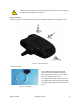
INTERFACES
OVERVIEW
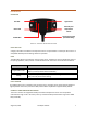
Red LED
Light Sensor
Green LED
Humidity and
Temperature
Sensor
Push Buon
Temperature Probe
(TP-100-TH Only)
FIGURE 3 – INTERFACE AND SENSOR LOCATIONS
PUSH BUTTON
A single push buon is located on the top of the sensor. The push buon is used to pair the sensor to a
compable Gateway. See the Pairing secon for operaon.
LEDS
Two LEDs (Red, Green) are located on the top of the sensor. The LEDs are used to indicate the status of
the pairing operaon, and to provide a visual indicaon when the sensor sends a wireless broadcast.
Operaon
LED Paern
Device Reset
Red (1 second), Green (1 second), OFF (1 second), Green (1 second)
Single Buon Press
Red (1 second): Device Not Paired to Gateway
Green (1 second): Device Paired to Gateway
Pairing
Red (1 second), Green (1 second): Successful Pairing
Red (1 second): Unsuccessful Pairing
Unpairing
Green (5 seconds), Red (Fast Flashing), Then Device Reset
LIGHT SENSOR
An ambient light sensor is located on the top of the sensor. The light sensor reports the percentage of
light exposed to the sensor, from 0% to 100%, where 100% is equivalent to approximately 220 Lux.
HUMIDITY AND TEMPERATURE SENSOR
The sensor contains an integrated humidity and ambient temperature sensor. The temperature
measurement range is -40 °C to 120 °C (± 0.5 °C), and the humidity measurement range is 0 to 100%
RH (± 3.5% RH).