
Maintenance Guide Part 3


NeTIS MAINTENANCE GUIDE – Version 1.1 73/139
8.2.1 O
PERATING PRINCIPLES
Link type: always G703
Type of module in charge of the link: COM 3/4
Normal operations: (see §9.1.2.2)
Each NeTIS-N appliance transmits data to the NeTIS-Bs on an it in both directions of the loop
and extracts data from the NeTIS-Bs only from one direction at a time
Each NeTIS-B appliance transmits data to the NeTIS-Ns on an it in both directions of the
loop and extracts data from the NeTIS-Ns only from one direction at a time depending on the
preferred direction selected in the settings
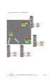
More precisely, the COM3 or COM4 board plays the role of G703 interface on the BS side
and the SWITCH side, it permanently transmits on both G703 junctions; The signal received
at these junctions are analysed and the indicators on the front face make it possible to know
the state of these junctions:
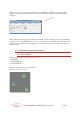
'ERR’ indicator: red indicator lighting when a line error is detected on the junction or
if there is no 2Mb/s signal (disconnection for example).
Yellow 'Rx’ indicator: flashes when a G704 synchronisation is detected; stays on
when a synchronisation is detected and the link with the switch is established.
Carte(s)
COM
Carte(s) COM
Carte
COM
Carte
COM
Carte
COM
Carte
COM
SWITCH
Site 1
Site 2
Site 3
Site i
REBOUCLAGE