User Manual & Installation Instructions LG-10 thru LG-30 IMPORTANT – READ ALL INSTRUCTIONS BEFORE OPERATING All steam boilers are built in accordance with ASME miniature boiler code. NOTE: It is the responsibility of the installer to conform to any state or local codes. If further inspection, following modification by installer, is required under state or local codes, that is the responsibility of the local installer. www.electrosteam.com rev.
WARNING - The following labels have been placed on this boiler for YOUR SAFETY. Failure to observe these instructions could lead to PROPERTY DAMAGE, SEVERE INJURY, or even DEATH CAU T ION HO T DANGER HIGH VOLTAGE AUTHORIZED PERSONNEL ONLY PELIGRO ALTO VOLTAJE SOLAMENTE PERSONAL AUTORIZADO REPLACE GLASS EVERY SIX MONTHS CAUTION USE ELECTRICAL SUPPLY CONDUCTORS RATED FOR A MINIMUM OF 90°C CA U T I O N THROW OFF MAIN POWER SWITCH BEFORE WORKING ON ELECTRICAL CABINET A MANUAL WAS SHIPPED WITH THIS BOILER.
LG-10 thru LG-30 - User Manual Electro-Steam Generator Corp. TABLE OF CONTENTS 1.) INSTALLATION INSTRUCTIONS .................................................................... 4 2.) OPERATION & SEQUENCE OF EVENTS ..................................................... 5 3.) CLEANING & MAINTENANCE ................................................................... 6-14 MANUAL “BLOW DOWN” ..................................................................................... 6 CLEANING WATER LEVEL PROBES ....
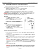
LG-10 thru LG-30 - User Manual Electro-Steam Generator Corp. 1.) INSTALLATION INSTRUCTIONS LITTLE GIANT “LG-SERIES” The Electro-Steam Generator design consists essentially of a high pressure chamber filled with water that is heated by one or more submerged resistance type electric heating elements. Automatic controls are provided to maintain the pre-set operating pressure and water level.
LG-10 thru LG-30 - User Manual Electro-Steam Generator Corp. 2.) OPERATION & SEQUENCE OF EVENTS IMPORTANT – READ INSTALLATION INSTRUCTIONS BEFORE OPERATING 1. Turn on water supply from the source to the Generator. 2. OPEN all valves on the Generator except for the Manual Drain (#19). 3. Place main disconnect switch in ON position. 4. Place ON/OFF Switch (#2) in ON position. 5. • The Water Solenoid (#7) [and Pump (#8), if high pressure] will engage and the chamber will begin to fill with water.
LG-10 thru LG-30 - User Manual Electro-Steam Generator Corp. 3.) CLEANING & MAINTENANCE The following cleaning procedures are HIGHLY RECOMMENDED in order to keep your Steam Generator in the best operating condition at all times. 3.1) MANUAL “BLOW DOWN” A Manual “Blow Down” is an easy way to GREATLY extend the life of your Steam Generator. Using a Motorized Auto-Flush & Drain (MAFD) of course helps, but is not a “Cure all”.
LG-10 thru LG-30 - User Manual Electro-Steam Generator Corp. 3.2) CLEANING WATER LEVEL PROBES (Continued) 6. 7. 8. 9. Clean probes to remove rust and scaling. NOTE: To clean probes you may use wire wheel, wire brush, steal wool, or Scotch-Brite. (Wire wheel works the best) You may also want to try some sort of chemical like CLR remover or LIME-A-WAY. Reinstall probes assuring each probe’s length is assigned to its proper letter.
LG-10 thru LG-30 - User Manual Electro-Steam Generator Corp. 3.4) REPLACING GLASS GAUGE & RUBBER WASHERS OR GLASS PACKINGS The Sight Glass (#10) gives the operator the ability to easily monitor the actual water level inside the chamber. If the Sight Glass (#10) gets clogged or is no longer functional, it can be very difficult to troubleshoot a problem. 3.4.
LG-10 thru LG-30 - User Manual Electro-Steam Generator Corp. 3.4) REPLACING GLASS GAUGE & RUBBER WASHERS OR GLASS PACKINGS (Continued) The Sight Glass (#10) gives the operator the ability to easily monitor the actual water level inside the chamber. If the Sight Glass (#10) gets clogged or is no longer functional, it can be very difficult to troubleshoot a problem. 3.4.
LG-10 thru LG-30 - User Manual Electro-Steam Generator Corp. 3.5) CHAMBER CHEMICAL/ACID TREATMENT All Electric Steam Generator should be cleaned regularly. The following is the least amount of times recommended to clean out your chamber: NORMAL WATER AREAS – Should be done ONCE A YEAR. BAD WATER AREAS – Should be done TWICE A YEAR.
LG-10 thru LG-30 - User Manual Electro-Steam Generator Corp. 3.5) CHAMBER CHEMICAL/ACID TREATMENT (Continued) 4. Close Manual Drain (#19) and Steam Out (#16); turn generator on until Sight Glass (#10) shows that it is 1/2 full, and then shut off. 5. Insert funnel into coupling, where Safety Valve (#18) used to be. 6. Pour a 1/2 Gallon of hydrochloric acid (inhibited) solution (NON-FOOD APPLICATIONS) into funnel very slowly, being careful of fumes and venting while pouring.
LG-10 thru LG-30 - User Manual Electro-Steam Generator Corp. 3.6) PRESSURE CONTROL DATA SHEET DEFINITIONS: “CONTROL” PRESSURE CONTROL – This pressure control should be the only one controlling the operating pressure of the generator. “SAFETY” PRESSURE CONTROL – This pressure control is only used if the “Control” fails. It is always set higher than the “Control”; if the operating pressure is passed, The “Safety” will turn the heaters off.
LG-10 thru LG-30 - User Manual Electro-Steam Generator Corp. 3.7) SETTING THE PRESSURE CONTROLS SETTING PRESSURE CONTROLS INSTUCTIONS: WARNING – The pressure controls must be set while all circuits are live. TO AVOID ELECTRICAL SHOCK, DO NOT TOUCH the wires or the terminals in which they connect while setting the pressure controls. NOTES: - Setting the pressure controls greatly relies on your ability to tell whether the contactor(s) are turning the heaters on or off.
LG-10 thru LG-30 - User Manual Electro-Steam Generator Corp. 3.7) SETTING THE PRESSURE CONTROLS (Continued) 5. At this point the contactor(s) should be clicked off and you should be able to click them on and then off again by pressing the SAFETY RESET. This is a way to test if the “SAFETY” is still controlling the pressure, and not the “CONTROL”.
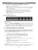
LG-10 thru LG-30 - User Manual Electro-Steam Generator Corp. 4.) CALCULATIONS AND DATA SHEETS 4.1) HEATER POWER & VOLTAGE RATINGS LG Model units use 3 Heaters to meet the required (KW) POWER from the customer’s specified INPUT VOLTAGE. Each heater comes in 5 different (KW) POWER RATINGS and 4 different VOLTAGE RATINGS. AVAILABLE HEATER RATINGS KW 3.33 5.00 6.50 8.33 9.
LG-10 thru LG-30 - User Manual Electro-Steam Generator Corp. 4.3) AMPERAGE CALCULATIONS The INPUT VOLTAGE, PHASE, TOTAL POWER RATING, and HEATER VOLTAGE RATING are used to calculate the amperage. NOTE: 380-425V heaters are not usually rated for 380-425V. They are usually 208-240V heaters that have been re-stamped 380-425V and wired in series.
LG-10 thru LG-30 - User Manual Electro-Steam Generator Corp. 4.4) ACTUAL POWER RATING CALCULATIONS Because the HEATER VOLTAGE RATINGS only come in 4 different voltages, and there are so many different voltages in the field, the TOTAL POWER RATING is only completely accurate if the VOLTAGE IN is exactly equal to the HEATER VOLTAGE RATING. This means, in most cases, the TOTAL POWER RATING is not completely accurate. The AMERAGE and INPUT VOLTAGE can be used to calculate the ACTUAL POWER RATING.
10 19 7 17 16 6 18 14 11 SIDE VIEW 9 CONTROL 15 12 SAFETY 3 2 1.) 2.) 3.) 5.) 6.) 7.) 1 13 SAL NEGRO CHRISTOPHER FERRARA JOHN PARDINI APPROVED: 06-19-07 06-19-07 DWG NO.
10 7 17 16 6 20 9 CONTROL 14 15 12 5 PSI 11 21 SIDE VIEW 18 SAFETY 3 2 1.) 2.) 3.) 5.) 6.) 7.) 1 13 SAL NEGRO CHRISTOPHER FERRARA JOHN PARDINI APPROVED: SAFETY 2 06-19-07 06-19-07 DWG NO.
6 10 8 19 7 17 16 18 14 11 SIDE VIEW 9 CONTROL 15 12 SAFETY 3 2 1.) 2.) 3.) 5.) 6.) 7.) 1 13 10 SAFETY MODEL UNIT: SAL NEGRO CHRISTOPHER FERRARA JOHN PARDINI APPROVED: 06-19-07 06-19-07 DWG NO.
6 19 10 8 7 17 16 20 9 CONTROL 14 15 12 5 PSI 11 21 SIDE VIEW 18 SAFETY 3 2 1.) 2.) 3.) 5.) 6.) 7.) 1 13 19 10 MODEL UNIT: SAL NEGRO CHRISTOPHER FERRARA JOHN PARDINI APPROVED: SAFETY 2 06-19-07 06-19-07 DWG NO.
CONTROL CONTROL SAFETY CLEARANCE TO SERVICE WATER LEVEL PROBES SAFETY DRAWING TITLE: CLEARANCE FOR HEATER SERVICE This drawing and all information therein are the property of Electro-Steam Generator Corp. and shall not be disclosed, in whole or in part, to any third party without prior permission of Electro-Steam Generator Corp. 22 of 33 SAL NEGRO JOHN PARDINI CHECKED: ENGINEER: APPROVED: DWG NO.
CONTROL CONTROL 5 PSI SAFETY CLEARANCE TO SERVICE WATER LEVEL PROBES SAFETY SAL NEGRO JOHN PARDINI CHECKED: ENGINEER: APPROVED: DWG NO.: 08-27-07 08-27-07 08-27-07 LG 10-30 HIGH PRESSURE MOTORIZED AUTO-FLUSH & DRAIN - MODEL UNIT: CHRISTOPHER FERRARA DRAWN BY: (INSTALLATION DATA) LG (L)(MAFD) 421-010-030-000110 SHEET: 1 OF 1 SCALE: N/A CLEARANCE HOLES FOR ELECTRIC SERVICE 2.
CONTROL CONTROL SAFETY CLEARANCE TO SERVICE WATER LEVEL PROBES SAFETY DRAWING TITLE: CLEARANCE FOR HEATER SERVICE This drawing and all information therein are the property of Electro-Steam Generator Corp. and shall not be disclosed, in whole or in part, to any third party without prior permission of Electro-Steam Generator Corp. 24 of 33 SAL NEGRO JOHN PARDINI CHECKED: ENGINEER: APPROVED: DWG NO.
CONTROL CONTROL 5 PSI SAFETY CLEARANCE TO SERVICE WATER LEVEL PROBES SAFETY SAL NEGRO JOHN PARDINI CHECKED: ENGINEER: APPROVED: DWG NO.: 07-16-07 07-16-07 07-16-07 LG 10-30 HIGH PRESSURE MOTORIZED AUTO-FLUSH & DRAIN - MODEL UNIT: CHRISTOPHER FERRARA DRAWN BY: (INSTALLATION DATA) LG (H)(MAFD) 421-010-030-000210 SHEET: 1 OF 1 SCALE: N/A CLEARANCE HOLES FOR ELECTRIC SERVICE 2.
G A C C PPL NO NC 26 of 33 YEL BLK BLUE BLUE YEL BLK OPTIONAL MANUAL LOWWATER RESET 1 AMP FUSE ON/OFF TOGGLE SWITCH DRAWING TITLE: RED RED RED RED LLCO H RED YEL SAL NEGRO CHRISTOPHER FERRARA JOHN PARDINI CHECKED: APPROVED: 09-12-07 09-12-07 DWG NO.
G C 27 of 33 WATER SOLENOID BLUE 5PSI PRESSURE CONTROL (NC) 1 3 YEL BLK 4 5 MOTORIZED AUTO-FLUSH & DRAIN 2 BLUE 6 ORG YEL PPL G YEL SAL NEGRO CHRISTOPHER FERRARA JOHN PARDINI APPROVED: 09-12-07 09-12-07 DWG NO.
G C C NO PPL 28 of 33 YEL BLK NO NC BLK YEL BLUE YEL BLK BLUE WATER SOLENOID GRN OPTIONAL MANUAL LOWWATER RESET ON/OFF TOGGLE SWITCH DRAWING TITLE: RED RED LLCO H RED YEL SAL NEGRO CHRISTOPHER FERRARA JOHN PARDINI CHECKED: APPROVED: 09-12-07 09-12-07 DWG NO.
C PPL 29 of 33 WATER SOLENOID YEL BLK NC BLUE 5PSI PRESSURE CONTROL (NC) 1 3 YEL BLK 4 5 MOTORIZED AUTO-FLUSH & DRAIN 2 BLUE 6 ORG YEL PPL YEL SAL NEGRO CHRISTOPHER FERRARA JOHN PARDINI APPROVED: 09-12-07 09-12-07 DWG NO.
26131 13067 10007 10004 - 3POLE 20AMP CIRCUIT BREAKER - 50AMP CONTACTOR - 3.33KW 208V HEATERS -or- 3.33KW 240V HEATERS 26135 13069 10039 10009 - 3POLE 40AMP CIRCUIT BREAKER - 75AMP CONTACTOR - 6.5KW 208V HEATERS -or- 6.5KW 230V HEATERS 26138 13069 10013 10040 T2 T1 - 3POLE 30AMP CIRCUIT BREAKER - 50AMP CONTACTOR - 5KW 208V HEATERS -or- 5KW 230V HEATERS (1) (1) (3) (3) T3 L3 26137 13069 10104 10011 - 3POLE 50AMP CIRCUIT BREAKER - 75AMP CONTACTOR - 8.33KW 214V HEATERS -or- 8.
26119 13069 10007 10004 - 2POLE 63AMP CIRCUIT BREAKER - 75AMP CONTACTOR - 3.33KW 208V HEATERS -or- 3.33KW 240V HEATERS T3 - 100AMP TERMINAL BLOCK - 3POLE 30AMP CIRCUIT BREAKERS - 50AMP CONTACTORS - 5KW 208V HEATERS -or- 5KW 230V HEATERS 13061 26132 13067 10043 - 100AMP TERMINAL BLOCK - 3POLE 25AMP CIRCUIT BREAKERS - 50AMP CONTACTORS - 9.75 KW 480V HEATERS (1) (2) (2) (3) 13061 26135 13069 10105 - 100AMP TERMINAL BLOCK - 3POLE 40AMP CIRCUIT BREAKERS - 75AMP CONTACTORS - 13.
(1) 13067 - 50AMP CONTACTOR (1) 13059A - 30AMP 600V CLS-R FUSE BLOCK (3) 13011A - 25AMP 600V CLS-RK5 FUSES (3) 10050 - 6.5KW 600V HEATERS (3PH) 20KW - (550-600V) (1) 13067 - 50AMP CONTACTOR (1) 13059A - 30AMP 600V CLS-R FUSE BLOCK (3) 13040A - 12AMP 600V CLS-RK5 FUSES (3) 10006 - 3.33KW 600V HEATERS (3PH) 10KW - (550-600V) L2 T2 L1 T1 T3 L3 (1) 13069 - 75AMP CONTACTOR (1) 13056A - 60AMP 600V CLS-R FUSE BLOCK (3) 13012A - 35AMP 600V CLS-RK5 FUSES (3) 10044 - 9.
ELECTRO-‐STEAM GENERATOR CORPORATION TERMS AND CONDITIONS OF SALE EXCLUSIVE AND ENTIRE: The following Standard Terms and Conditions are intended by the parties to govern all the purchases of equipment, parts or service from Seller, and together with the specifications provided or embodied herewith, represent the entire understanding of the parties
within twelve (12) months of supplying such service, repair or part, Seller shall at its option, repair or replace EXW (Ex works), such defective part or parts.
EQUITY, ON STATUE, AT LAW OR ON ANY OTHER THEORY OF LAW, SHALL NOT EXCEED THE PAID CONTRACT PRICE. THE BUYERACKNOWLEDGES THAT THE REMEDIES PROVIDED IN THIS CONTRACT ARE EXCLUSIVE AND IN LIEU OF ALL OTHER REMEDIES AVAILABLE TO THE BUYERAT LAW, IN CONTRACT, IN TORT, IN STATUTE OR IN EQUITY OR IN ANY OTHER THEORY OF LAWS.