COMPONENTS PART FIGURE DESCRIPTION | QTY | PART FIGURE DESCRIPTION TOP PANEL | 1PC fl LEFT DOOR | 1PC B I LEFT SIDE PANEL | 1PC | J FRAMER FACE | 1PC ¢ 0 RIGHT SIDE PANEL| 1PC BOTTOM PANEL BOTTOM RAIL | 1PC | M <7 DEARER a TOM | tre F g BACK PANEL | PCS | N <> DARNER SACK ORAN ER SUTTON | 1pg | ~ DORMER SUTTON | gps H RIGHT DOOR | 1PC
HARDWARE & TOOLS PART FIGURE DESCRIPTION | QTY | PART FIGURE DESCRIPTION | QTY 1 Ny WOODEN DOWEL | PCS | 10 > SCREW PCs 8*30 94%25 2 Vy WOODEN DOWEL | PCS | 11 & SHELF PIN | PCs PE*30 3 oo CAM BOLT | 14PCS| 12 a SCREW PCS B32 4 ® CAM LOCK | PCS | 13 Cr, ANCHOR 1PC #15%12 5 oS CAM LOCK | PCS | 14 & SCREW PCS 1599 P4*25 6 KNOB FIX BELT 1P¢ 7 x, KNOB BOLT | PCS | 16 WASHER PCS 8 SCREW pests | 17 ~~ PLASTIC BAR | 1PC #312 D=7 9 3° DRAWER STOPPER | PCS TOOL NEEDED: eT PHILIPS SCREWDRIVER REQUIRED SUGGESTION: « N
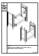
1. Screw Cam bolts (3) and insert dowels (1) into panel Insert dowels (1) to panel D as indicated. 3. Attach part E to panel D as indicated.
STEP 2: cure with cam locks (4). 2.
mg 16 PCS #3%12 D=7 STEP 4: 1. Attach panel Fs to the back of cabinet and secure with screws (8) as indicated. 2. Insert plastic bar (17) between the panel Fs as indicated. 3. Then finish securing the rest of screws (8).
5 2 12 Pes 6430 3 i 4 pes 5 4 PCS parallax STEP 5: 1. Screw cam bolts (3) & insert dowels (2) into panel J. 2. Insert dowels (2) to rail Os as indicated. 3. Attach part panel J and secure with cam locks (5). 4. Slide panel M to part indicated. 5. Attach panel N to part K.L & M and secure with screws {10}. 6. Attach knobs (6) to panel J with bolts (7).
STEP 6: 1. Insert drawer to the cabinet Rest ith drawer stoppers (9) as indicated. &C.