
User Manual

166
/
223
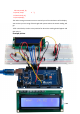
As we have eight LEDs and eight resistors to connect, there are actually quite a few
connections to be made.
It is probably easiest to put the 74HC595 chip in first, as pretty much everything else
connects to it. Put it so that the little U-shaped notch is towards the top of the
breadboard. Pin 1 of the chip is to the left of this notch.
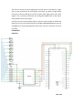
Digital 12 from the MEGA2560 goes to pin #14 of the shift register
Digital 11 from the MEGA2560 goes to pin #12 of the shift register
Digital 9 from the MEGA2560 goes to pin #11 of the shift register
All but one of the outputs from the IC is on the left side of the chip. Hence, for ease
of connection, that is where the LEDs are, too.
After the chip, put the resistors in place. You need to be careful that none of the
leads of the resistors are touching each other. You should check this again before
you connect the power to your MEGA2560. If you find it difficult to arrange the
resistors without their leads touching, then it helps to shorten the leads so that they
are lying closer to the surface of the breadboard.
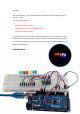
Next, place the LEDs on the breadboard. The longer positive LED leads must all be
towards the chip, whichever side of the breadboard they are on.
Attach the jumper leads as shown above. Do not forget the one that goes from pin
8 of the IC to the GND column of the breadboard.
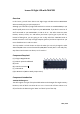
Load up the sketch listed a bit later and try it out. Each LED should light in turn until
all the LEDs are on, and then they all go off and the cycle repeats.
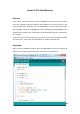
Code
After wiring, please open the program in the code folder- Lesson 24 Eight LED with
74HC595 and click UPLOAD to upload the program. See Lesson 2 for details about
program uploading if there are any errors.
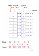
The first thing we do is define the three pins we are going to use. These are the
MEGA2560 digital outputs that will be connected to the latch, clock and data pins
of the 74HC595.
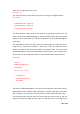
int latchPin = 11;
int clockPin = 9;
int dataPin = 12;
Next, a variable called 'leds' is defined. This will be used to hold the pattern of which
LEDs are currently turned on or off. Data of type 'byte' represents numbers using
eight bits. Each bit can be either on or off, so this is perfect for keeping track of