
User Manual

167
/
223
which of our eight LEDs are on or off.
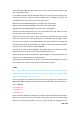
byte leds = 0;
The 'setup' function just sets the three pins we are using to be digital outputs.
void setup()
{
pinMode(latchPin, OUTPUT);
pinMode(dataPin, OUTPUT);
pinMode(clockPin, OUTPUT);
}
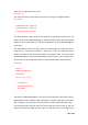
The 'loop' function initially turns all the LEDs off, by giving the variable 'leds' the
value 0. It then calls 'updateShiftRegister' that will send the 'leds' pattern to the shift
register so that all the LEDs turn off. We will deal with how 'updateShiftRegister'
works later.
The loop function pauses for half a second and then begins to count from 0 to 7
using the 'for' loop and the variable 'i'. Each time, it uses the Arduino function
'bitSet' to set the bit that controls that LED in the variable 'leds'. It then also calls
'updateShiftRegister' so that the leds update to reflect what is in the variable 'leds'.
There is then a half second delay before 'i' is incremented and the next LED is lit.
void loop()
{
leds = 0;
updateShiftRegister();
delay(500);
for (int i = 0; i < 8; i++)
{
bitSet(leds, i);
updateShiftRegister();
delay(500);
}
}
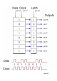
The function 'updateShiftRegister', first of all sets the latchPin to low, then calls the
MEGA2560 function 'shiftOut' before putting the 'latchPin' high again. This takes
four parameters, the first two are the pins to use for Data and Clock respectively.
The third parameter specifies which end of the data you want to start at. We are
going to start with the right most bit, which is referred to as the 'Least Significant