
User Manual


44
/
223
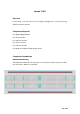
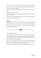
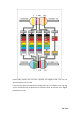
Breadboards come in various sizes and configurations. The simplest kind is just a
grid of holes in a plastic block. Inside are strips of metal that provide electrical
connection between holes in the shorter rows. Pushing the legs of two different
components into the same row joins them together electrically. A deep channel
running down the middle indicates that there is a break in connections there,
meaning, you can push a chip in with the legs at either side of the channel without
connecting them together. Some breadboards have two strips of holes running
along the long edges of the board that are separated from the main grid. These have
strips running down the length of the board inside and provide a way to connect a
common voltage. They are usually in pairs for +5 volts and ground. These strips are
referred to as rails and they enable you to connect power to many components or
points in the board.
While breadboards are great for prototyping, they have some limitations. Because
the connections are push-fit and temporary, they are not as reliable as soldered
connections. If you are having intermittent problems with a circuit, it could be due
to a poor connection on a breadboard.
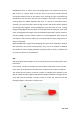
LED:
LEDs make great indicator lights. They use very little electricity and they pretty much
last forever.
In this lesson, you will use perhaps the most common of all LEDs: a 5mm red LED.
5mm refers to the diameter of the LED. Other common sizes are 3mm and 10mm.
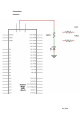
You cannot directly connect an LED to a battery or voltage source because 1) the
LED has a positive and a negative lead and will not light if placed the wrong way and
2) an LED must be used with a resistor to limit or 'choke' the amount of current
flowing through it; otherwise, it will burn out!