
User Manual


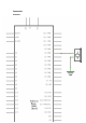

Although the bodies of the switches are square, the pins protrude from opposite
sides of the switch. This means that the pins will only be far enough apart when they
are placed correctly on the breadboard.
Remember that the LED has to have the shorter negative lead to the left.
Code
After wiring,please open program in the code folder- Lesson 5 Digital Inputs, and
press UPLOAD to upload the program. If errors are prompted, see Lesson 2 for
details about the tutorial on program upload.
Load the sketch onto your MEGA2560 board. Pressing the left button will turn the
LED on while pressing the right button will turn it off.
The first part of the sketch defines three variables for the three pins that are to be
used. The 'ledPin' is the output pin and 'buttonApin' will refer to the switch nearer
the top of the breadboard and 'buttonBpin' to the other switch.
The 'setup' function defines the ledPin as being an OUTPUT as normal, but now we
have the two inputs to deal with. In this case, we use the set the pinMode to be
'INPUT_PULLUP' like this:
pinMode(buttonApin, INPUT_PULLUP);
pinMode(buttonBpin, INPUT_PULLUP);
The pin mode of INPUT_PULLUP means that the pin is to be used as an input, but
that if nothing else is connected to the input, it should be 'pulled up' to HIGH. In
other words, the default value for the input is HIGH, unless it is pulled LOW by the
action of pressing the button.
This is why the switches are connected to GND. When a switch is pressed, it
connects the input pin to GND, so that it is no longer HIGH.
Since the input is normally HIGH and only goes LOW when the button is pressed, the
logic is a little upside down. We will handle this in the 'loop' function.
void loop()
{
if (digitalRead(buttonApin) == LOW)
{
digitalWrite(ledPin, HIGH);
}
if (digitalRead(buttonBpin) == LOW)
62 / 223