
Computer Accessories User Manual


MCE User’s Guide MCE windows and dialogs
NM20600A-A 2004-05-17 25
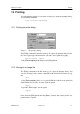
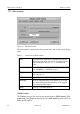
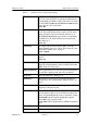
Table 4 Controls in the Pre-processing dialog
Filter frame The [Lowpass filter] toggle selects the filter. You can
select the cutoff frequency or transition width with the
corresponding text fields or sliders.The values are in Hz.
Use the [Freq. response] and [Impulse response] but-
tons to see the effect of the filter.
Units: Hz
Baseline frame The [Baseline] toggle and the corresponding text field
select the baseline period used to remove the DC offset
and in automatic selection of the bad channels (p. 4).
The [Detrend baseline] toggle and the corresponding
text field select the other baseline used for removing
slow drifts (p. 4).
Units: ms
[Decimate] The toggle button and text field or slider select the
down-sampling ratio. See section “Decreasing the com-
puting time and file sizes” on page 5.
Units: samples
[Trim] The toggle button and text field select the analysis
period.
Units: ms
[Bad channels] The toggle button and text field set the bad channels.
Write the channel numbers to the text field with format
‘MEG #### #### #### ####’
[Apply projection] If the toggle button is set, the noise projection defined in
the data file is applied to the data and calculations.
[Show all] Opens the MEG data -dialog (p. 26).
[Automatic] The button resets the projection and bad channels to
default values. See “Bad channels and projections” on
page 6.
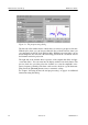
Preview frame The buttons let you select either a single channel or filter
properties in the preview plot
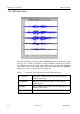
Preview plot Shows the selected information; original data in red and
processed data in blue. Left mouse button zooms in the
image, the [rescale] button reverts to automatic scaling.
X-axis units: ms in Channel and Impulse response
mode, Hz in freq. response mode.
Y-axis units: fT for magnetometers, fT/cm for gradiom-
eters.
[Cancel] Closes the window
[OK] Applies the new values and closes the window