
Operation Manual


Page 7
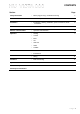
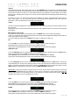
1 2 3
4 5 6
1 SOURCE selector
2 DISPLAY
3 VOLUME control
4 ON/STANDBY Button
5 IR RECEIVER window
6 DISPLAY AND LED functions button
7 8 9
10 11 12 13 14
7 LOUDSPEAKER OUTPUTS right
8 HT/AUX function selector for AUX1/HT
input
9 LOUDSPEAKER OUTPUTS left
10 XLR BALANCED inputs left and right
11 CD, AUX1/HT, AUX2, TUNER line input RCA
sockets
12 LINE OUT (fixed) output RCA sockets
13 PRE OUT (volume controlled) output RCA
sockets
14 IEC MAINS INPUT
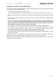
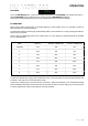
XLR Balanced input and output lead
connections:
(for reference, no XLR signal leads supplied)
Pin functions:
1 Ground (cable shield)
2 Normal polarity ("hot" or “+”)
3 Inverted polarity ("cold" or “-“)
FACILITIES & CONNECTIONS