
User Manual


2. PANEL LAYOUT AND CONNECTIONS
9
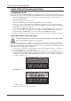
. REAR PANEL CONNECTIONS
101 2
3
4
5 6 7
8 9
1. POWER, Switch for turning the unit on and o.
2. DC IN, Input for power supply. Use the included PSU-3b power adapter connected to
a power outlet.
3. USB, For connecting the unit to a computer. Used for MIDI control or Overbridge.
Connect to a computer host using the included A to B USB 2.0 connector cable.
4. MIDI THRU/SYNC B, Forwards data from MIDI IN. Can also be configured to send DIN sync to legacy
instruments. Use a standard MIDI cable to connect another MIDI unit in the chain.
5. MIDI OUT/SYNC A, MIDI data output. Can also be configured to send DIN sync to legacy instruments.
Use a standard MIDI cable to connect to MIDI In of an external MIDI unit.
6. MIDI IN, MIDI data input. Use a standard MIDI cable to connect to MIDI Out of an
external MIDI unit.
7. CONTROL IN A/B Inputs for an expression pedal, footswitch, or CV. Use 1/4” mono phone plug for
CV signals.
8. INPUT L (mono)/R, Audio inputs. Use either 1/4” mono phone plug (unbalanced
connection) or 1/4” (Tip/Ring/Sleeve) phone plug (balanced connection).
9. OUTPUT L/R, Main audio outputs. Use either 1/4” mono phone plug (unbalanced
connection) or 1/4” (Tip/Ring/Sleeve) phone plug (balanced connection).
10. HEADPHONES, Audio output for stereo headphones. Use 1/4” (Tip/Ring/Sleeve)
phone plug.