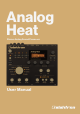
Analog Heat Stereo Analog Sound Processor User Manual
FCC compliance statement This device complies with part 15 of the FCC rules. Operation is subject to the following two conditions: (1) This device may not cause harmful interference, and (2) this device must accept any interference received, including interference that may cause undesired operation. NOTE: This equipment has been tested and found to comply with the limits for a Class B digital device, pursuant to Part 15 of the FCC Rules.
IMPORTANT SAFETY AND MAINTENANCE INSTRUCTIONS Please read these instructions carefully and follow the operating advice given here. 1. Do not use this unit near water. 2. Never use aggressive cleaners on the casing or the LCD screen. Remove dust, dirt and fingerprints with a soft, dry and non-abrasive cloth. More persistent dirt can be removed with a slightly damp cloth using only water. Disconnect all cables before doing this. Only reconnect them when the product is safely dry. 3.
TABLE OF CONTENTS TABLE OF CONTENTS 1. INTRODUCTION. . . . . . . . . . . . . . . . . . . . . . . . . . . . . . . . . . . . . . . . . . . . . . . . . . . . . . . . . . . . . . . . . . . . . . . . . . . . . . . . . . . . 7 1.1 CONVENTIONS IN THIS MANUAL . . . . . . . . . . . . . . . . . . . . . . . . . . . . . . . . . . . . . . . . . . . . . . . . . . . . . . . . . . . . . 7 2. PANEL LAYOUT AND CONNECTIONS. . . . . . . . . . . . . . . . . . . . . . . . . . . . . . . . . . . . . . . . . . . . . . . . . . . .
TABLE OF CONTENTS 6.6 SYSTEM. . . . . . . . . . . . . . . . . . . . . . . . . . . . . . . . . . . . . . . . . . . . . . . . . . . . . . . . . . . . . . . . . . . . . . . . . . . . . . . . . . . . 19 6.6.1 USB CONFIG. . . . . . . . . . . . . . . . . . . . . . . . . . . . . . . . . . . . . . . . . . . . . . . . . . . . . . . . . . . . . . . . . . . . . . . . . . . . . . . 19 6.6.2 USB AUDIO CONFIG. . . . . . . . . . . . . . . . . . . . . . . . . . . . . . . . . . . . . . . . . . . . . . . . . . . . . . . . .
1. INTRODUCTION 1. INTRODUCTION Thank you for purchasing Analog Heat. The Analog Heat is a stereo analog sound processor with many great features such as; 8 different analog effect circuits, an analog multimode filter, analog EQ, and support for Elektron’s groundbreaking software suite Overbridge. Its innovative combination of modern technology and tried and trusted ways of analog sound processing lets you add sparkly brilliance, or grimy roughness, to any sound source.
2. PANEL LAYOUT AND CONNECTIONS 2. PANEL LAYOUT AND CONNECTIONS 2.1 FRONT PANEL CONTROLS 1 2 3 4 5 6 7 8 21 9 20 10 19 11 12 18 17 16 15 14 13 1. MASTER VOLUME sets the master volume for the L/R and Headphones outputs. 2. [AMP] key accesses the AMP parameter page where you can set things such as drive amount and the volume of the preset. 3. [FILTER/EQ] key accesses the FILTER/EQ parameter pages where you, among other things, can set the filter frequency cutoff, and adjust the equalizer.
2. PANEL LAYOUT AND CONNECTIONS 2.2 REAR PANEL CONNECTIONS 1 2 3 4 5 6 7 8 9 10 1. POWER, Switch for turning the unit on and off. 2. DC In, Input for power supply. Use the included PSU-3b power adapter, connected to a power outlet. 3. USB, For connecting the unit to a computer. For MIDI-control or Overbridge use. Connect to a computer host using the included A to B USB 2.0 connector cable. 4. MIDI THRU/SYNC B, Forwards data from MIDI IN.
3. FIRST STEPS WITH THE ANALOG HEAT 3. FIRST STEPS WITH THE ANALOG HEAT 3.1 CONNECTING THE UNIT Make sure you place the Analog Heat on a stable support, such as a sturdy table with sufficient cable space. Before you start connecting the Analog Heat to other units, make sure all units are switched off. 1. Plug the supplied DC adapter to a power outlet and connect the small plug to the 12 V DC connector of the Analog Heat unit. 2. Connect the audio source to INPUT L/R. 3.
3. FIRST STEPS WITH THE ANALOG HEAT 3.3 SETUP EXAMPLES The Analog Heat is very well suited for use in both an analog setup and in a more digital environment. Here are a couple of examples of how you can use the Analog Heat. For additional information about how to set up Analog Heat in different configurations, please see "6.3.3 ANALOG IN/OUT" on page 16. 3.3.
4. SIGNAL FLOW 4. SIGNAL FLOW The illustrations below show the signal flows of the Analog Heat and illustrates how the different components interact with each other. 4.1 AUDIO SIGNAL FLOW This illustration shows the general flow of audio through the Analog Heat. The complete signal chain is in stereo. Multi-mode Filter Circuit Drive Equalizer Dirt Out L/R Bypass In L/R Effect Input Sensitivity Wet level Dry/Wet Mix Preset Volume Master Volume Headphones Overbridge 4.
5. THE USER INTERFACE 5.1.2 SAVING A PRESET 1. Press and hold PRESET/DATA for two seconds. The selected preset now starts to blink to illustrate that you are about to overwrite a preset position. 2. Turn PRESET/DATA to select the preset slot to where you want to save your sound, and then press [YES] 3. (Optional) Turn PRESET/DATA to the character you wish to edit. Press and hold [SETTINGS] and then turn PRESET/DATA to move the cursor to the desired character and select it by releasing [SETTINGS].
5. THE USER INTERFACE 5.6 DRIVE Sets the gain level in the effect circuit. A higher setting increases the effect of the selected circuit type, typically resulting in more distortion. For more information, please see "4. SIGNAL FLOW" on page 12. 5.7 WET LEVEL Sets the level of the signal coming from the effect. It is applied before the DRY/WET mix. It is used to match the level of the dry signal for easy mixing of the two. For more information, please see "4. SIGNAL FLOW" on page 12. 5.
6. THE SETTINGS MENU 5.13 OVERBRIDGE This manual primarily focuses on how to use the Analog Heat as a standalone effect. But you can also use Overbridge to interact with the Analog Heat. The Overbridge software suite enables a tight integration between the Analog devices (Analog Rytm, Analog Keys, Analog Four, Analog Heat) and a computer DAW. N.B. You must have Analog Heat OS 1.02 or later, and Overbridge 1.15 or later to run Overbridge with Analog Heat.
6. THE SETTINGS MENU • HIGH (Maximum input level 2,5 V, peak to peak) • MAX (Maximum input level 1,2 V, peak to peak) 6.2 MODULATION Here you can connect a number of modulation sources with their destinations and set the modulation depth. For more information, please see "APPENDIX B: MODULATION SOURCES AND DESTINATIONS" on page 29. 1. Turn the PRESET/DATA knob to scroll through the source list, and then select it by pressing PRESET/ DATA or [YES]. 2.
6. THE SETTINGS MENU Analog Heat supports 4 channels of audio. Analog Input L/R are routed to the analog in-, and outputs, and can optionally also be routed through the effect. FX Send L/R are always routed to the effect. • AUTO In Auto mode, Analog Heat automatically detects if the Overbridge plugin is running or not. With Overbridge running, the Analog In is not routed through the effect to the Analog Out. (Same as OFF setting.
6. THE SETTINGS MENU 6.4.2 CONTROL IN B The available settings are the same as for CONTROL IN A mentioned above. 6.5 MIDI These settings are stored in the global settings and are not part of the preset. 6.5.1 SYNC • CLOCK RECEIVE Sets whether or not the Analog Heat responds to MIDI clock and transport sent from external devices. (ON, OFF) • CLOCK SEND Sets whether or not the Analog Heat sends/forwards MIDI Clock and transport.
6. THE SETTINGS MENU • ENCODER DEST Sets whether or not the DATA ENTRY and LEVEL knobs send MIDI data. • INT MIDI Only sends data internally. • INT + EXT MIDI Sends data both internally and externally. • PARAM INPUT Makes it possible to control Analog Heat parameters from an external MIDI device sending CC/NRPN data. (ON, OFF) 6.5.3 CHANNELS • MIDI CHANNEL Sets the MIDI channel that Analog Heat uses to send and receive MIDI data. When set to OFF, all MIDI functionality is disabled. (Range 1—16) 6.
7. PARAMETER PAGES The device should be turned on at least 2 hours before you perform a calibration for its circuits to warm up properly. If the unit has not yet warmed up for 2 hours, there is a calibration countdown counter which automatically initiates the calibration once it reaches the timeout. Also, please note that nothing should be connected to the device during the calibration. Remember to turn down the volume on all speakers and headphones before activating Test mode.
7. PARAMETER PAGES 7.2.2 RESO Sets the amount of resonance at the cutoff point of the filter. (Range 0.00—127.00) 7.2.3 ENV Sets the amount of how much the envelope and envelope follower affects the filter frequency. A negative value gives an inverted modulation. (Range -128.00—127.00) 7.2.4 LFO Sets the amount of how much the LFO affects the filter frequency. A negative value gives an inverted modulation. (Range -128.00—127.00) 7.3 FILTER/EQ PAGE 2 Press [FILTER/EQ] twice to access this parameter page.
7. PARAMETER PAGES 7.4.1 MODE Sets the mode of the envelope follower. Keep turning the knob to access the next mode. The higher the value under the selected mode, the more gain is added to the signal, which is useful for weak input signals. • AR (Attack-Release) Creates an envelope control signal where the Attack phase begins when the incoming sound exceeds the threshold.
7. PARAMETER PAGES 7.4.3 REL In Follow (FLW) mode, this is the fall time of the envelope follower, i.e. how quickly the follower falls when the amplitude of the audio falls. In generator mode (AD or AR), this is the decay- or release time of the generated envelope. The fall time of the underlying envelope follower is set to a good, predefined fall time in these configurations. (Range 0—127) 7.4.4 TRIG Sets the threshold level at which the envelope follower triggers the envelope generator and the LFO.
7. PARAMETER PAGES 7.5.4 DEPTH1 Sets the amount of how much the envelope follower affects the modulation destination. A negative value gives an inverted modulation. (Range -128.00—127.00) 7.6 LFO PAGE 1 Press [LFO] once to access this parameter page. 7.6.1 SPEED Sets the rate of the LFO in relation to the internal or external tempo. It is synced to BPM if one of the “BPM x” settings are selected in the MULT parameter. To sync the LFO to straight beats, try settings of 16 or 32.
8. TIPS & TRICKS 7.7.1 FADE FADE offers the possibility to fade in/out the LFO modulation. Positive values give a fade-out, negative values give a fade-in. A middle position (0) results in no fade in/out. The fade curve is restarted each time the LFO triggers. For more information, please see "7.4.4 TRIG" on page 23. (Range -64—63) 7.7.2 MODE Selects between four different modes of LFO behavior. • FREE is the default free-running mode. The LFO run continuously, never restarting or stopping.
8. TIPS & TRICKS 4. Start by setting DRIVE to 0, WET LEVEL to 127, and DRY/WET to 127. 5. Press the [AMP] key to access AMP PAGE, and set VOL to 127. 6. Press the [ENV] key to access ENVELOPE PAGE 1, and set MODE to AD. Adjust the MODE (AD) parameter until you clearly see the incoming signal in the TRIG meter. You should see the peaks and dips of the incoming signal, retaining as much as possible of dynamics of the signal. 7.
9. TECHNICAL INFORMATION 9. TECHNICAL INFORMATION ELECTRICAL SPECIFICATIONS HARDWARE Impedance balanced audio outputs Main outputs level: +22 dBu peak Output impedance: 440 Ω unbalanced 122 x 32 pixel back-lit LCD MIDI In/Out/Thru with DIN Sync out 2 x 1/4” impedance balanced audio out jacks 2 x 1/4” balanced audio in jacks 1 x 1/4” stereo headphone jack 2 x 1/4” control input jacks 48 kHz, 24-bit D/A and A/D converters Electrically isolated Hi-speed USB 2.0 port Power inlet: Center positive 5.5 x 2.
APPENDIX A: MIDI APPENDIX A: MIDI This appendix lists the CC and NRPN numbers for the Analog Heat.
APPENDIX B: MODULATION SOURCES AND DESTINATIONS APPENDIX B: MODULATION SOURCES AND DESTINATIONS This appendix lists parameters that can be modulated by one or more of the following modulation sources; Envelope/Envelope Follower, LFO, and Expression pedal/CV.
INDEX INDEX A ACTIVE MODE 13 AMPLIFIER 20, 25 Drive 20 Dry/Wet 20 Volume 20 Wet 20 AUDIO & ROUTING 16 C CALIBRATION 19 CONNECTIONS 9 CONTROL INPUTS 17 CREDITS AND CONTACT INFORMATION 27 CV 17 E EFFECT CIRCUITS 13 ENVELOPE (FOLLOWER) 21 Attack 22 Base 23 Filter 23 Mode: Attack-Decay 22 Mode: Attack-Release 22 Mode: Follow 22 Modulation depth 24 Modulation destination 23 Release 23 Trigger 23 Width 23 EQUALIZER 21 EQ High 21 EQ Low 21 EXPRESSION PEDAL 17 F FILTER Dirt 21 Env modulation 21 Filter types 21
8419ENG-B