INSTALLATION MANUAL CUPIDO 60 & CUPIDO 70 CONVENTIONAL FLUE FIRES P L E A S E L E AV E T H E S E I N ST R U CT I O N S B E H I N D W I T H T H E D E V I C E
I N STA L L AT I O N M A N UA L D O N OT US E T H I S P R O D U CT A S A P R I M A RY H E AT S O U R C E 2
I N STA L L AT I O N M A N UA L CONTENTS 1 CE STATEMENT 2 IMPORTANT SAFETY INFORMATION 3 WARRANTY 4 REMOTE CONTROL WITH FULL ELECTRONIC IGNITION 4.1 Adjusting the communication code 4.2 Igniting the pilot light 4.3 Igniting the main burner 4.4 Switching off the fireplace 5 INSTALLATION PREPARATION AND - INSTRUCTION 5.1 Relevant norms and guidelines 5.2 Attention points gas fireplace 5.3 Attention points gas connection 5.4 Requirements flue and wall terminals 5.
I N STA L L AT I O N M A N UA L 1 CE STATEMENT 2 IMPORTANT SAFETY INFORMATION We hereby declare that the design and construction of the Element4 gas appliances are complying to the essential demands and regulations for gas products. The fireplace may only be installed by a qualified installer/dealer, following these installation instructions. We advise you to read these instructions properly, before commencing the installation of your device.
I N STA L L AT I O N M A N UA L 3 WARRANTY NB: Should a problem occur, that you are not able to fix yourself with the help off the support in Appendices A to C, please contact you installer or dealer. The Element4 devices on which this warranty is applicable are made of high quality materials. Should any problem or defects still occur the following provision are in effect; 1. 2. 3. Before any installation, the installer will ensure himself of the good quality and operation of the flue channel.
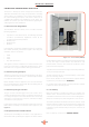
I N STA L L AT I O N M A N UA L 4 REMOTE CONTROL WITH FULL ELECTRONIC IGNITION The unit is operated using a remote control (Fig. 4.1) or the Element4 Puck, connected to a receiver (Fig. 4.2). The receiver is powered by 4 pen lite (type AA) batteries or a 6V adapter; 2 penlight batteries (type AAA) are used for the remote control. The life of the batteries is about a year with normal use. AM PM 1 2 ON OFF 4.
I N STA L L AT I O N M A N UA L 5 INSTALLATION PREPARATION AND - INSTRUCTION The device is developed, tested and approved conform the applicable standards for the usage, the performance and safety of the product. The installation of your device must apply to the current building prescriptions. We advise to make use of a qualified gas installer for the installation of your device. The installer can provide you with all information regarding the safety regulations of the installation. 5.
I N STA L L AT I O N M A N UA L 6 FIRE SAFE INSTALLATION D To install a gas fireplace as safely as possible, several installation preparations need to be made. This overview can be used to assure the fire safety of a conversion of a fireplace. C Before commencing Installation, confirm that the details on the appliance data plate correspond to the local distribution conditions, gas type and pressure to which the appliance is to be installed.
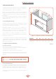
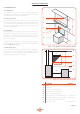
I N STA L L AT I O N M A N UA L 6.3 Building the Fireplace Construct a studwork fireplace to the desired sizes, minimum sizes are shown in figure 6.1. Any combustible material used to construct the Fireplace must not be closer than the minimum dimensions quoted in table 6.1. H The appliance should be fitted with a minimum clearance of 100mm (G in figure 6.2) from any combustible objects or materials; this includes any combustible materials used for the fireplace construction.
I N STA L L AT I O N M A N UA L 6.5 Additional notes 6.5.1 Ventilation This appliance does not need extra air vent. However an adequate supply of fresh air to maintain temperatures and a comfortable environment is recommended. 1 c 6.5.2 Floor protection The temperature of the floor under the device needs be less than 85°C and the floor of the conversion around the fireplace is to be constructed of non-flammable materials.
I N STA L L AT I O N M A N UA L 7 ATTENTION POINTS GAS FLUE 8 INSTALLATION CHECK AND FIRST USAGE To guarantee the fire safety regarding you flue gas configuration a casing is necessary. For this case non-combustible materials should be used. Make sure to ventilate a shaft and never to insulate it, to make sure the hot air is able to get away. 8.
I N STA L L AT I O N M A N UA L 10 MAINTENANCE INSTRUCTION This part of the manual focuses on maintenance. To ensure the optimal flame picture of your device, an annual maintenance by a competent company or installer is prescribed. 10.1 Maintenance in the combustion chamber During maintenance the glass windows of the fire need to be removed. To do this follow the following steps: 10.1.1 (Dis)assembly of the trims For a tight finish of the fireplace, trims are available.
I N STA L L AT I O N M A N UA L 1 Figure 10.3 - Remove bottom trim Figure 10.5 - Put on the suction cup and lift window 2 Figure 10.4 - Remove window ropes 13 Figure 10.
I N STA L L AT I O N M A N UA L 9 ELECTRICAL CIRCUIT Figure 9.1 shows a simplified connection circuit for the fireplace. Every fireplace is provided with a main adapter. # Omschrijving (1) Gas Block (2) Receiver (3) Main Burner (4) Log Burners (5) Pilot set (6) Adapter 6V (7) Wifi-Box The app has a user friendly, interactive layout and the design is adjusted for Element4 devices.
I N STA L L AT I O N M A N UA L 11 DECORATION ARRANGEMENT Only the decoration ceramics supplied with this appliance are to be used. The ceramics must be laid only as shown on this page. Replacement parts are available from your dealer, but should only be installed by a qualified installation engineer. An elaborate decoration instruction is found on the sheet in the logset that comes with the fire. These instructions show you how to decorate the fire step by step.
I N STA L L AT I O N M A N UA L 12 USER INSTRUCTION We recommend that you have the appliance inspected annually by a recognized installer to ensure safe use and a long service life guarantee 12.1 Hand over to the customer • • • • • User manual Installation manual Instruction card decoration material Suction cups Remote control 12.2 Maintenance instructions for the installer Below is an overview of the minimum maintenance that must take place annually; • Remove the glass plate and remove all ceramic parts.
I N STA L L AT I O N M A N UA L 13 COMMISSIONING THE APPLIANCE 14 SERVICING 13.1 Pilot Ignition Check 1. Ignite the pilot light as described in the User Instructions 2. Check that the pilot flame stays alight 3. Extinguish the pilot light Turn the appliance OFF and isolate the gas supply. Ensure the appliance is fully cold before attempting to start servicing the appliance. No liability can be accepted by Element4 for injury caused by burning or scolding by a hot appliance. 13.2 Main Burner Check 1.
APPENDICES A FIRST AID FOR MALFUNCTION Below you will find an overview of the possible cause and solution in the event of a failure. Problem A No transmission (motor will not run) Possible Cause Solution 1 Batteries in the receiver empty Replace the batteries (4x 1.5V AA) 2 Batteries hand remote empty Replace the batteries (2x 1.
APPENDICES Figure A.1: RESET-button Figure A.4: Antenna Figure A.2: Bend pin Figure A.5: Torx screw AM PM 1 2 ON OFF 40mm Figure A.6: Testpoint A Figure A.3: “Double plus”-button on the remote 19 Figure A.
APPENDICES Problem G The pilot light goes on but goes out immediately when the main burner switches on Possible Cause Solution 1 Insufficient voltage across the thermocouple or too much resistance in the thermocouple circuit Place the measuring pins of the multimeter on the ground and black cable of the breaker. This value must be at least 4.5 mV. See again Figure A.8.
APPENDICES 4,5 mV 4,5 mV Figure A.11: SI-port Figure A.8: interrupter MODE CONTACT Ignition Main Burner 1&3 High Flames 1 Pilot 3 Extinguish Main Burner Ignite second burner 1, 2 & 3 Extinguish second burner 2&3 1&2 3 MA GR MO SW PANEL RECEIVER Figure A.9: Wiring receiver Cable G60-ZCE/1000 2 1 Figure A.12: Domotica system Figure A.
APPENDICES B ERRORS CODES PROCONTROL APP B.1 Messages shown in app Error code F02 F03 Message in App Description Possible cause Contact Service. • • 5 sec. beep from Receiver Fire is not responding; no ignition • • • • Microswitch not making contact with cam on motor knob Motor wiring is incorrect Reversed polarity or faulty Microswitch Bent Motor Knob • • • 5 sec.
APPENDICES Error code Message in App Description Possible cause F31 Contact Service.
APPENDICES C FAULTS AND ERROR CODES IN THE REMOTE This appendix can be consulted when error messages occur in the application for smartphone and tablet. C.1 F41 error This message will appear if there is no or bad Wi-Fi reception, this can be between app and router or Wi-Fi box and router By closing the App and opening it again, this is solved in most cases. Cause The cause may be that the ProControl module is blocked or is too far away from the router. See: router information.
APPENDICES D LOCATION TERMINAL D.1 Terminal location with vertical exhaust (B11) Distance Exhaust 1,2 of 3 At the same roof level > 6m * At a different roof level > 3m * & ** On a lower wall > 2m * On a higher sloping surface > 6m *** “Distance” = minimum distance required to position the exhaust in order to prevent adverse effects in relation to; 1. A ventilation opening of a used room, toilet or bathroom 2. Supply of heated air when the supply flows through a used room. 3.
APPENDICES E TECHNICAL DATA The dataplate specifies for which type of gas, gas pressure and for which country this appliance is intended. The nameplate is attached to a chain. It must remain attached to the chain. Note: Check whether the appliance is suitable for the gas type and gas pressure on site.
APPENDICES F ECODESIGN Since 1 January 2018 every fireplace has been provided with an eco-label which is always supplied with the fireplace. The ecolabel shows which category the fireplace belongs to. F.1 Ecolabels The ecolabels for the different types of gas are indicated below, respectively G20, G25 and G30.
APPENDICES G DIMENSIONAL DRAWINGS On the following ones you will find dimensional drawings of the conventional flue Cupido models with some of the important dimensions that you have to take into account when installing and installing your fireplace. When you install the Cupido models in an existing chimney, there are two possible exhaust ports, respecively on top and on the back of the fireplace. One of the both needs to be open, the other is than closed off.
APPENDICES Figure I.
APPENDICES Figure I.
E L E M E N T 4 B .V. Paxtonstraat 23 8013 RP Zwolle The Netherlands Info@element4.nl www.element4fires.