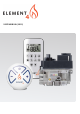
USER MANUAL (2019)
USER MANUAL CONTENTS IMPORTANT SAFETY INFORMATION Important safety information..................................................... 4 HANDSET Technical Data ........................................................................ 5 General Notes ......................................................................... 5 10 BUTTON REMOTE Setting Fahrenheit or Celsius ................................................. 6 Setting the Time .......................................................................
IMPORTANT SAFETY INFORMATION Read these instructions carefully and completely before installing or operating. Failure to follow them could result in a fire or explosion causing property damage, personal injury, or loss of life. Service and installation must be performed by a trained / experienced service technician. WHAT TO DO IF YOU SMELL GAS ▪ Do NOT operate any appliance. ▪ Do NOT touch any electrical switch; do NOT use any phone in your building.
USER MANUAL HANDSET The Symax system combines new technology and a modern design with ease of operation. Instead of scrolling through a confusing menu, each function can now be activated by touch-ing a symbol. Many remote controls on the market have few buttons and require extensive programming to operate. The Symax System uses the same easy-to-operate logic – find the symbol for the function you want and touch that symbol – but the Symax now has new tactile buttons for an immediate, positive response.
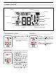
10-SYMBOL OPERATION Child Proof Time Signal Indicator Thermostatic Mode Battery Status AM PM Fan Countdown Timer Fahrenheit or Celsius Program Mode Light ON OFF 1 2 Eco Mode Temperature Auxiliary Feature (2nd Burner Feature) Figure 1: 10-symbol Display SETTING FAHRENHEIT or CELSIUS AM PM To change between °C and °F, press and buttons simultaneously. NOTE: Choosing °F results in a 12 hour clock. Choosing °C results in a 24 hour clock.
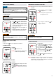
USER MANUAL MANUAL MODE (HANDSET) NOTICE BEFORE OPERATING 1. Make sure MANUAL knob on the GV60 valve is in the ON, full counterclockwise position. 2. Place the ON / OFF switch (if equipped) in the I (ON) position. DESIGNATED LOW FIRE and HIGH FIRE NOTE: Backlight must be on for high fire and low fire double-click operation. AM ▪ To go to low fire, double-click ton. is displayed. but- NOTE: Flame goes to high fire first before going to low fire.
MODES of OPERATION AM PM ON OFF 1 2 AM PM ON OFF Thermostatic Mode he room temperature is measured and T compared to the set temperature. The ���height is then automatically adjusted to achieve the set temperature. PROGRAM MODE AM PM AM AM PM ON OFF ON OFF OFF: 1. Press or or button to enter Manual Mode. 2. Press button to enter Thermostatic Mode. 3. Press button to enter Eco Mode.
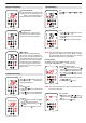
USER MANUAL AUXILIARY FEATURE (2ND BURNER FEATURE) SELECTED AM PM ON OFF 1 2 ON TIME SETTING (PROGRAM 1): 7. , , displayed, is displayed shortly, and hour flashes. 8. To select hour press or button. button. , , 9. To confirm press displayed, displayed shortly, and minutes flash. 10. To select minutes press or button. 11. To confirm press button.
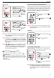
THE PUCK LIGHT / DIMMER OPERATION AM ON: Press button ( on at preset level. OFF: Press The Puck is a smart control that works in conjunction with the GV60 / Symax system. Its basic functions include turning the fire on and off and turning the flame height up and down. displayed). Light is ON/OFF button ( disappears). SETTING: 1. Press button and hold until flashes. 2. To adjust light between 20…100 % press button. or 3. To confirm setting either press button or wait ( displayed).
USER MANUAL SYNCHRONISATION HANDSET/RECEIVER 1. Insert batteries or connect AC mains power. The module for circulating fan and light / dimmer includes a mains adapter. With mains adapter, batteries can be used for backup. 2. Place ON / OFF switch (if equipped) to ON position. 3. The Receiver has to learn the Handset code: Press and hold the Receiver’s reset button (see figure 19, page 11) until you hear two (2) beeps. After the second, longer beep, release the reset button.
WI-FI BOX A new version of the Wi-Fi Box has been created. The improvements include faster processing speed, new Wi-Fi chip, and best of all for the customer, an uncomplicated and much shorter App Setup menu for the ProControl app. The new Wi-Fi Box also has variable power supply between 5 and 24 volts, two RGB outlets, identical connectors on both ends of the cable, and the Wi-Fi Box itself has a much smaller footprint for easy installation in tight spaces. MINIMUM REQUIREMENT SMART DEVICE: ▪ IOS 8.
USER MANUAL MYFIRE WI-FI BOX (B6R-W2…) RGB LED'S AND LED DRIVER TECHNICAL DATA Indirect connection ( >5 A) 5 - 24 VDC direct from the LED driver to the LEDs Connection of data output (DO) and ground (GND) from the LED RGB control output of the Wi-Fi Box to the RGB LEDs. (see figure 6) RGB LED WORKING VOLTAGE RANGE 5 - 24 VDC SUPPORTED RGB LED COUNT PER RGB-CHANNEL 300 NOTICE There is no standard for RGB LED controller. Therefore, the RGB LEDs or RGB LED-stripes have to be tested for functionality.
PROCONTROL APP SETUP NOTICE For ProControl App Setup, you will need your Wi-Fi network SSID and password. INITIAL SETUP 1. Download ProControl app from Apple App Store or Google Play Store. 2. Touch screen to start App Setup. 3. Choose language, temperature (°C or °F) and time format (12 or 24 hour). REGISTRATION NOTE: You must register before logging in. Registration is one time only. 1. Fill in data and accept the “Privacy Policy”. 2. Touch “OK” in pop-up notice. 3.
Paxtonstraat 23 8013 RP Zwolle The Netherlands +31-(0)38 420 90 20 info@element4.