
Instruction manual


-42-
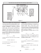
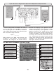
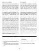
STATIC MEASUREMENTS
Figure 38
Q3 BIAS
TP15
V
COM V
With the power turned OFF, connect your VOM to the
circuit as shown in Figure 38. Set your VOM to read
9 volts DC and turn the power ON. The DC voltage
at the base of Q3 should be approximately 1.8 volts.
If your answer varies by more than 2 volts, turn the
power OFF and check components R7, R8, R11 and
Q3.
If you don’t have an RF generator and oscilloscope,
skip to the FM Oscillator Assembly Procedure.
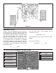
AC GAIN
The AC gain of the mixer is set by the impedance of
the primary side of T1 and by the current flowing in
Q3. The current in Q3 is set by the resistors R7, R8
and R11. Connect your test equipment to the circuit
as shown in Figure 39. Your scope probe must have
an input capacitance of 12pF or less, otherwise the
probe will detune T1 resulting in an incorrect
measurement. Set your scope to read 10mV per
division. Set your RF generator at 10.7MHz no
modulation minimum voltage output. Turn the power
ON and slowly increase the amplitude of the
generator until 4 divisions or 40mVpp are seen on
the scope. With an alignment tool or a screwdriver,
adjust T1 for peak. Reduce the generator amplitude
to maintain 4 divisions on the scope. Move the scope
probe to the base of Q3 and record the input voltage
here:
Vb = __________mVpp.
Turn the power OFF. The gain can be calculated as
follows:
AC Gain = 40mV / Vb.
Your calculated answer should be about 3.
Record your calculation:
AC Gain = __________
Because the signal from the oscillator is injected at
the emitter of Q3, the emitter resistor is not bypassed
to ground. This is why the gain of the mixer is low
compared to the other IF stages.