
Instruction manual

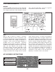

is heard. Place the iron end of the “magic wand” near
L3. If the station is heard, it means that L3 needs
less capacitance. Carefully adjust the FM oscillator
trimmer located on the back of the gang until the
station is heard. Repeat this step until the pointer is
aligned to the station’s frequency. Adjusting both the
oscillator coil L3 and the oscillator trimmer capacitor
will effect the oscillator’s frequency, so it is advisable
to repeat this procedure until the FM oscillator
alignment is optimized. This process sets the FM
oscillator range at 98.7MHz to 118.7MHz.
RF ALIGNMENT
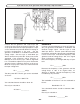
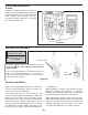
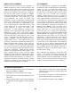
Press together L1 and L2. Spread apart coil L1 so
that it resembles Figure 45. The gaps or spaces
should be between 1/32” and 1/16” wide. This
procedure sets the tracking of the RF section. Use the
special coil spacer provided to gap the coil as shown.
Carefully slide the coil spacer between the coils to get
the spacing shown in Figure 45.
This concludes the alignment of the FM radio section.
If no stations are heard, verify that FM signals are
present in your location by listening to another FM
radio placed near the superhet 108. If the FM section
is still not receiving go back and check each stage for
incorrect values and for poor soldering.
-48-
Approx.
1/16” gap
Approx.
1/16” gap
Figure 45
Figure 46
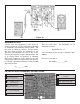
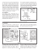
Turn the power ON. Slowly increase the amplitude of
the generator until a 1kHz signal is seen on the
scope. Keep the generator at a low level of output to
prevent the IF sections from limiting. With an
alignment tool or screwdriver, adjust T1 for a peak on
the scope. Reduce the amplitude of the input signal
if necessary. Adjust T2 for a peak and reduce the
amplitude of the input signal if necessary. Repeat
these steps until the IF alignment is optimized. This
procedure aligns the FM IF amplifiers to 10.7MHz.
TP15
Hz
Generator
TP15
Short the base of Q2 to the
emitter (as shown below).
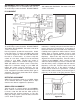
ALIGNMENT WITH RF GENERATOR AND OSCILLOSCOPE
IF ALIGNMENT
Spacer
Top View
L1 L2
L1
L2
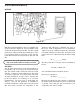
Switch to the FM section. Connect your RF
generator and oscilloscope to the circuit as shown in
Figure 46. Set your RF generator at 10.7MHz
modulated at 1kHz deviation with minimum voltage
output. Set the scope to read 50mV per division.
With a clip lead, short the base emitter junction of
Q2. This short “kills” the local oscillator.