
Instruction manual


-3-
Dice are the most ancient gambling implement
known to man, and the most universal, having been
known in nearly all parts of the world since earliest
times. Today they are used in some games of skill,
such as backgammon, but are used chiefly in
gambling games. In the United States the most
popular dice game is Craps.
Each die consists of seven light emitting diodes
(LEDs). Since there are two dice, we need 14
LEDs. The trick is to light the right LEDs to give the
six possible dice combinations.
The Pocket Dice kit consists of three main circuits.
They are (1) a clock oscillator, (2) a presettable
counter and (3) a decoder circuit.
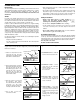
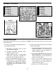
Figure 1 shows a block diagram of the functions.
We will study each function and get an
understanding on how the Pocket Dice kit works.
Referring to Figure 1, the clock puts out a series of
pulses at about 60 per second. The counter IC2
receives the clock pulses and outputs 0’s or 1’s on
pins 4, 5 and 6. The outputs can represent any one
of six combinations 000, 001, 010, 110, 111 or 101.
Each time the clock puts out a pulse, the output of
the counter changes. The 0’s and 1’s are fed to the
decoder circuit which transforms the 0 and 1
combinations into a series of lit LEDs to display the
die patterns. Pin 13 of IC2 changes state once
every time the IC passes through the six state
sequence. Thus, it puts out a pulse at a frequency
of one-sixth of the digital clock or 10 pulses per
second. This signal is fed the input of IC3 and
becomes its clock input. IC3 and its decoder work
the same as IC2 except at a slower clock rate.
THE CLOCK FUNCTION
Figure 2 shows the diagram of the clock circuit. It
consists of two NAND gate digital integrated
circuits. In our circuit, the two inputs are tied
together which forms an inverter circuit. When the
input of IC1A is low, the output will be high, thus
when the input of IC1B is high, its output will be low.
This output is fed to the input of IC1A via capacitor
C1 and is called positive feedback, a key element to
make a circuit oscillate. The frequency of oscillation
depends on the value of capacitor C1 and resistor
R1. The value chosen results in a frequency of
approximately 60 cycles per second. The output at
IC1B will be a square wave.
In the Pocket Dice
kit, we want the
oscillator to run for a
short time. As long
as the oscillator is
running, the dice
will be constantly
changing numbers.
The number changes once with every cycle, or 60
times per second. For the dice to come up with a
number, we must stop the clock. This is done by
shorting out the feedback with switch SW1. Once
the switch is closed, the clock will stop and a
random number will appear on the dice.
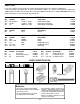
THE PRESETTABLE COUNTER FUNCTION
IC2 and IC3 are the presettable counters. These
counters convert the clock pulses in six
combinations of “1” and “0”. These IC’s have a
single input at pin 14 and three outputs on pins 4, 5
and 6. With every pulse change at the input, the
output will change as shown in Figure 3. Note the
corresponding dice number as the result of the 0
and 1 output of pins 4, 5 and 6.
By tying pin 6 to pin
1, we programmed
the counter to put out
only 6 combinations
as shown in Figure 3.
Every time the clock
puts out a pulse, the
counter will change
its output. On the
first pulse, the
counter pins 4 and 5
will be low (0) and pin
6 will be high (1).
This results in the die number two. The next clock
pulse will result in the counter output of all lows (0)
and the die will show the number one. Thus, the
sequence continues until all six numbers are shown.
CIRCUIT DESCRIPTION
INTRODUCTION
Figure 1
Figure 2
Figure 3
4 5 6
0 0 1
0 0 0
0 1 0
1 1 0
1 1 1
1 0 1
Output Pins
Clock Pulse
1
2
3
4
5
6
First Die Second Die
IC2 IC3
Counter 1
Counter 2Clock
Decoder 1
Decoder 2
4 5 6 4 5 6
IC1
A
IC1
B
R1
C1S1