
Instruction manual


-7-
TROUBLESHOOTING
Contact Elenco
®
Electronics if you have any problems. DO NOT contact your place of purchase as they will not
be able to help you.
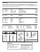
D1 - LED (red)
D2 - LED (red)
D3 - LED (red)
D4 - LED (red)
D5 - LED (red)
D6 - LED (red)
D7 - LED (red)
(see Figure E)
D8 - LED (red)
D9 - LED (red)
D10 - LED (red)
D11 - LED (red)
D12 - LED (red)
D13 - LED (red)
D14 - LED (red)
(see Figure E)
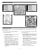
ASSEMBLY CONTINUED
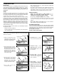
Figure E
Mount the LED with the flat
side in the same direction as
marked on the PC board.
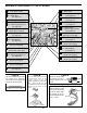
1. One of the most frequently occurring problems is
poor solder connections.
a) Tug slightly on all parts to make sure that
they are indeed soldered.
b) All solder connections should be shiny.
Resolder any that are not.
c) Solder should flow into a smooth puddle
rather than a round ball. Resolder any
connection that has formed into a ball.
d) Have any solder bridges formed? A solder
bridge may occur if you accidentally touch
an adjacent foil by using too much solder or
by dragging the soldering iron across
adjacent foils. Break the bridge with your
soldering iron.
2. Be sure that all components have been mounted
in their correct places.
a) Be sure that diodes D15-D19 have not been
installed backwards. The band on the
diodes should be in the same direction as
shown on the top legend.
b) Be sure that LEDs D1-D14 have not been
installed backwards. The flat side on the
LEDs should be in the same direction as
shown on the top legend.
c) Have the ICs been inserted into their
sockets correctly? The notch or dot on the
ICs should be in the same direction as
shown on the top legend.
d) Be sure to use a fresh 9-volt battery.
Mount flush
with PC board
Foil Side of PC Board
Flat