Copyright © 2008 by Elenco® Electronics, Inc. All rights reserved. No part of this book shall be reproduced by any means; electronic, photocopying, or otherwise without written permission from the publisher.
Table of Contents Basic Troubleshooting 1 Parts List How to Use It 2 Advanced Troubleshooting 9 3 Project Listings 10 Projects #1-63 About Your Snap Circuits® Parts 4, 5 How It Works 6, 7 General Operating Instructions DO’s and DON’Ts of Building Circuits ! WARNING: SHOCK HAZARD - Never connect Snap Circuits® to the electrical outlets in your home in any way! 7 Other Snap Circuits® Products 11-43 44 2. Be sure that parts with positive/negative markings are positioned as per the drawing.
Parts List (Colors and styles may vary) Symbols and Numbers Important: If any parts are missing or damaged, DO NOT RETURN TO RETAILER. Call toll-free (800) 533-2441 or e-mail us at: help@elenco.com. Customer Service • 150 Carpenter Ave. • Wheeling, IL 60090 U.S.A. ID Name 5 1 11 Part # Qty.
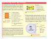
How To Use It Install six “AA” batteries (not included) into the bottom of the Rover body and one 9V battery (not included) into the remote control unit. Install the antenna into the remote control unit by screwing it in. Antenna Remote control Front of Rover – There is also a 1-snap wire that is used as a spacer or for interconnection between different layers. A large clear plastic base grid is included with this kit to keep the circuit blocks together, it fits on top of the Rover body.
About Your Snap Circuits® Parts ! Warning to Snap Circuits® owners: Do not use parts from other Snap Circuits® sets with this kit. The Snap Rover® uses higher voltage which could damage those parts. Page 44 and our website www.snapcircuits.net has approved circuits that you can use. (Part designs are subject to change without notice). The base grid is a platform for mounting parts and wires.
About Your Snap Circuits® Parts (continued) The Sound & Recording IC (U9) module contains an integrated recording circuit, a dual timer integrated circuit for making audio tones, microphone, speaker, filtering circuitry, and other supporting components. It includes resistors (adjustable and fixed), capacitors, transistors and diodes that are needed to make the recordings and play all the sounds. Recording time is up to 12 seconds.
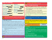
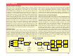
How It Works Remote Control Transmitter: When the levers in the Remote Control Unit are pushed, electrical contacts are made connecting the 9V battery power to the transmitter, indicating which commands the user wants sent to the Rover. Forwards/Backwards commands for each set of wheels and two extra functions are controlled by different levers or buttons.
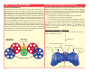
How It Works (continued) General Operating Instructions Rover Drive Mechanism: Build the circuit for Project #1. Set the channel switches on the remote control unit and Deluxe Receiver module (RX2) to the same setting (A, B, or C). Place the Rover on a flat, open area, turn the ON/OFF switch on the remote control unit and the slide switch (S1) to ON, and extend the antenna on the Remote Control.
DO’s and DON’Ts of Building Circuits After building the circuits given in this booklet, you may wish to experiment on your own. Use the projects in this booklet as a guide, as many important design concepts are introduced throughout them. Every circuit will include a power source (the batteries), a resistance (which might be a resistor, motor, integrated circuit, etc.), and wiring paths between them and back.
Advanced Troubleshooting (Adult supervision recommended) Elenco® Electronics is not responsible for parts damaged due to incorrect wiring. If you suspect you have damaged parts, you can follow this procedure to systematically determine which ones need replacing: 6. Sound & Recording IC (U9) and the 1μF and 100μF capapacitors (C7, C4N): Build Project #62 (Lunar Messenger); the parts should work as described in it. 7.
Project Listings Project # 1 2 3 4 5 6 7 8 9 10 11 12 13 14 15 16 17 18 19 20 21 22 23 24 25 26 27 28 29 30 31 32 Description Space Rover Sound Disable Rover Fun Sounds Rover Spooky Sounds Rover Simple Sounds Not So Simple Sounds Space Sounds Audio Recorder One Sound Lighthouse Rover Remote Sound Remote Sound Switcher Parallel Pitch Reducer Series Pitch Reducer Resistor Row Ways to Light a Light Nightlite Rover Remote Drive Rover Tone Flicker Clicker Flicker Volume Control Electronic Metronome Flickering M
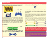
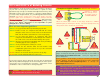
Project #1 Space Rover OBJECTIVE: To build a remote control vehicle. ! Turn knobs to adjust sound. ROVER REAR + WARNING: Moving parts. Keep face and eyes away from the front of the disc launcher and from flying discs. Microphone Cha nnel sw i ol unit. nt r co n remot ho e tc Be sure to route the jumper wires under U9 as shown. Snap Circuits®: The Snap Circuits® Kit uses electronic blocks that snap onto a clear plastic base grid to build different circuits.
Project #2 Sound Disable Rover OBJECTIVE: annoying. To turn off the space sounds when they get Added part to circuit. Modify the Project #1 circuit by adding a second slide switch (S1) over the U9 sound and recording IC, using two 1-snaps as shown. The circuit works the same as before except turning on the new S1 switch shuts off the space sounds.
Project #3 Fun Sounds Rover ROVER REAR OBJECTIVE: To make cute sounds. Cha nnel sw i Parts in the circuit: ol unit. nt r co n remot ho e tc Parts you can replace them with: ! -13- WARNING: Moving parts. Keep face and eyes away from the front of the disc launcher and from flying discs. Modify the Project #2 circuit by adding a the 100μF capacitor (C4N) over the 10K resistor (R4), using a 1-snap as shown. The circuit works the same as before except that the space sounds sound a little different.
Project #4 Spooky Sounds Rover ROVER REAR OBJECTIVE: To turn change the space sounds. Cha nnel sw i Added part to circuit. ol unit. nt r co n remot ho e tc Part in the circuit: Parts you can replace it with: Modify the Project #2 circuit by adding a the 100μF capacitor (C4N) over the 10K resistor (R4), using a 1-snap as shown. The circuit works the same as before except that the space sounds sound a little different. Turn knobs on U9 to change the sound.
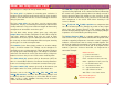
Project #5 Simple Sounds Turn knob to adjust pitch. Project #6 ROVER REAR OBJECTIVE: To make sounds electronically. Build the circuit with the base grid centered on the Rover body, and connect the jumper wires as shown. Turn on the slide switch (S1). The recorded message may play, followed by a tone. Turn the lower knob on the sound & recording IC (U9) to adjust the pitch (frequency) of the tone. Not So Simple Sounds Turn knobs to adjust sound.
Project #7 Space Sounds ROVER REAR OBJECTIVE: To make exciting sounds. Project #8 Build the circuit with the base grid centered on the Rover body, and connect the jumper wires as shown. Turn on the right slide switch (S1). Turn the knobs on the sound & recording IC (U9) to make a variety of space sounds. Audio Recorder OBJECTIVE: To make an electronic recording and play it back. Keep OFF. Slide to ON to record message, then slide back to OFF.
Project #9 One Sound OBJECTIVE: To make sound for a while. Build the circuit with the base grid centered on the Rover body, and connect the jumper wires as shown. TURN THE KNOBS on U9 TO THE LEFT setting. Turn on the slide switch (S1), the recorded message (if any) may play. ROVER REAR Turn knobs to the LEFT setting. + Push the press switch; a tone is heard for a few seconds and then shuts off. You can adjust how long the tone plays for by turning the upper U9 knob a little to the right.
Project #11 Remote Sound OBJECTIVE: To make sound for a while. ROVER REAR + Build the circuit with the base grid centered on the Rover body, and connect the jumper wires as shown. TURN THE KNOBS on U9 TO THE RIGHT setting. Turn on the slide switch (S1). Turn on the remote control unit and extend the antenna. Push the right button on the remote control; a tone is heard for a few seconds and then shuts off. You can adjust how long the tone plays for by turning the upper U9 knob a little to the left.
Project #13 Parallel Pitch Reducer ROVER REAR OBJECTIVE: To show how resistors work. Project #14 Turning on the switch places the 100 ohm resistor (R1) in parallel with the 10K ohm resistor (R4), changing the resistance which controls the pitch of the tone. Build the circuit with the base grid centered on the Rover body, and connect the jumper wires as shown. Set the upper knob on the U9 to the middle and the lower knob to the right.
Project #15 Resistor Row ROVER REAR OBJECTIVE: To learn about resistors. + Project #16 When the slide switches are off the larger resistors (R2 and R4) are connected in a series, limiting the flow of electricity to the white LED. Turning on the slide switches bypasses the larger resistors and the LED gets brighter. Connecting resistors in a series increases the resistance. Build the circuit and connect the jumper wires as shown.
Project #17 Nightlite Rover + ROVER REAR OBJECTIVE: To drive around in the dark. B Build the circuit (being sure to connect all eight colored jumper wires), and turn on the right slide switch (S1). Use the levers on the remote control unit to drive Rover around. The white LED (D4) in front acts as a headlight, so you can use it in a dark room. If the left slide switch is off then you will hear a tone. Turn the knobs on the sound & recording IC (U9) to change the tone.
Project #19 Tone Flicker B + Build the circuit and connect the jumper wires as shown, note that the 1KΩ resistor (R2) is underneath the 100μF capacitor (C4N). Turn on the right slide switch (S1), you hear a tone and the white LED (D4) flashes. Turn on the left slide switch to shut off the tone and push the press switch (S2) to stop the flashing. Project #20 Clicker Flicker OBJECTIVE: To hear sounds and flash lights.
Project #22 Electronic Metronome OBJECTIVE: To learn about metronomes. ROVER REAR Build the circuit and connect the jumper wires as shown. Turn on one of the slide switches (S1) and adjust lower knob on the sound & recording IC (U9). The left switch adds the 100μF capacitor (C4N) to the circuit, which regulates the sound to be a slow clicking. The left switch adds the smaller 1μF capacitor (C7) to the circuit, giving a much faster clicking.
Project #24 Not So Often Timer ROVER REAR OBJECTIVE: To make cute sounds. Project #25 Build the circuit and turn on the right slide swtich (S1). Use the knobs on the sound & recording IC (U9) to adjust the tone. Push and hold the press switch (S2) to change the sound from a tone to clicking. Turn on the left slide switch to lower the clicking rate, by adding the 100μF capacitor (C4N) to the circuit. Stop & Light + ROVER REAR OBJECTIVE: To make cute sounds.
Project #26 Quad Red Blinker ROVER REAR OBJECTIVE: To make cute sounds and flash lights. Project #27 Build the circuit and turn on the right slide swtich (S1). The red lights in the Rover body are blinking and a tone is heard. Use the knobs on the sound & recording IC (U9) to adjust the blink rate and tone. Turn on the left slide switch to shut off the sound. Quick-Slow Blinker ROVER REAR OBJECTIVE: To make cute sounds and flash lights.
Project #28 Super Blinker OBJECTIVE: To make a flashing circuit. A B Build the circuit and connect the jumper wires as shown. Turn on the right slide switch (S1) to flash lights and make sound. Use the knobs on the sound & recording IC (U9) to adjust the blink rate and tone. You can shut off the sound by turning on the left slide switch. You can change the sound by replacing the 100Ω resistor (R1) with the 10KΩ resistor (R4). Project #30 Noisy Flasher OBJECTIVE: To make a flashing circuit with sounds.
Project #32 Car Alarm OBJECTIVE: To make cute sounds and flash lights. B ROVER REAR A Build the circuit and turn on the slide swtich (S1). Lights in the Rover body are blinking and a sound like a car alarm is heard. Use the knobs on the sound & recording IC (U9) to adjust the blink rate and tone. For more fun, add the 1KΩ resistor (R2) across the points marked A & B using a single snap.
Project #34 Recording Blinker + ROVER REAR OBJECTIVE: To make a flashing circuit. Build the circuit and connect the jumper wires as shown. Turn on the right slide switch (S1) to flash lights and make sound. Use the knobs on the sound & recording IC (U9) to adjust the blink rate and tone. Push the press switch (S2) to play the recording. Turn on the left slide switch and talk into the microphone to change the recording; turn it off when finished.
Project #36 Remote Control Flasher ROVER REAR OBJECTIVE: To sounds and lights remotely. Use the buttons on the remote control unit to stop the sound or blinking. ntrol unit. co on remote ch annel sw it Ch Build the circuit and connect all the jumper wires as shown. Be sure the deluxe receiver (RX2) and remote control unit are set to the same channel and turn on the slide swtich (S1). Lights in the Rover body are blinking and a tone is heard.
Project #38 Remote Control Right Lite OBJECTIVE: To use remote control. ROVER REAR + Project #39 Press the buttons on the remote control to light the white LED (D4), note that it shines to the side. The left button will make it brighter. If you push the press switch (S2), then the remote control buttons do not light the LED. ntrol unit. co annel sw it Ch on remote ch Build the circuit and connect the jumper wires as shown. Turn on the remote control unit and extend the antenna.
Project #40 Current Diverter OBJECTIVE: To learn about electric current. Build the circuit and connect the jumper wires as shown. Turn on the remote control unit and extend the antenna. Turn on the right slide switch (S1) and hold down the right button on the remote control unit; you hear a tone (it may be prceded by a recording). ROVER REAR + Turn on the left slide switch to change the tone and light the white LED (D4).
Project #42 Multi-Tone Rover ROVER REAR OBJECTIVE: To control sounds using remote control. Build the circuit and connect the jumper wires as shown. Turn on the remote control unit and the slide switch (S1). Use the remote control levers to drive Rover around. Press the buttons on the remote control to change the tone. You can also adjust the tone using the knobs on the sound & recording IC (U9). Project #43 Remote Sound & Light + ntro l unit.
Project #44 Double Launcher OBJECTIVE: To send two foam discs flying at a time. Build the circuit and place discs inside the disc launcher (DL). Turn on the slide switch (S1) nothing happens yet. ROVER REAR + Push the press switch (S2) for a moment; a motor starts up, the “eyes” start blinking, and the white LED (D4) lights. Push the press switch again and usually two discs are launched (not just one).
Project #46 Groovy Launcher OBJECTIVE: To send foam discs flying and play tones. + ROVER REAR Build the circuit and place discs inside the disc launcher (DL). Turn on both slide switches (S1). Adjust the knobs on the sound & recording IC (U9) for sounds you like. The white LED (D4) blinks rapidly. Push the press switch (S2) to start up the disc launcher and then again to launch discs. Position the launcher so that discs will not fly toward people, animals, or objects.
Project #48 Venus Visitor OBJECTIVE: To build a remote control vehicle with voice recording and cute sounds - like a visitor from Venus! ROVER REAR + Build the circuit and connect the 8 jumper wires as shown (C4N will hang over the edge of the base grid). Turn on the remote control unit and the slide switch (S1). Use the remote control levers to drive Rover around and adjust the tone sounds using the knobs on the sound & recording IC (U9).
Project #49 Easy Rover ROVER REAR OBJECTIVE: To build a simple remote control vehicle. + Cha nnel sw i Press the left button on the remote control to light the white LED (D4). You can use it to see ahead when exploring in the dark. ol unit. nt r co n remot ho e tc Build the circuit and connect the jumper wires as shown. Turn on the remote control unit and extend the antenna. Turn on the slide switch (S1) and use the remote control levers to drive Rover around.
Project #51 Jupiter Jumble ROVER REAR OBJECTIVE: To build a remote control vehicle with sounds and lights. Build the circuit and connect the jumper wires as shown. Turn on the remote control unit and the slide switches (S1). Use the remote control levers to drive Rover around and adjust the tone sounds using the knobs on the sound & recording IC (U9). The white LED (D4) will be flashing on some settings. annel sw it Ch + Project #52 Press the buttons on the remote control to change the tones.
Project #53 Generator OBJECTIVE: To produce electricity by spinning the wheels. Flip the Rover body so it is upside down and connect the jumper wires to the body and circuit as shown. Turn off the slide switch (S1) for the time being. Now turn on the slide switch (S1) and spin the right wheels again. The wheels now take more effort to spin, and cause the left wheels to also spin. + Spinning the right wheels makes all the inter-connected gears spin, and spins the shaft on the right motor.
Project #55 Write Your Parts ROVER REAR OBJECTIVE: To draw resistors in different shapes. Shapes to be drawn. Use a SHARP No. 2 pencil, draw on a hard surface, press hard and fill in several times for best results. Build the circuit at left and connect the jumper wires to it, but leave the loose ends of the red and black jumper wires unconnected for now. There is one more part you need and you are going to draw it. Take a pencil (No. 2 type is best but other types will also work).
Project #58 Frequency Resistors OBJECTIVE: To use capacitors like resistors to control the volume of sound. ROVER REAR Build the circuit and connect the jumper wires as shown. You hear a tone, use the switches (S1 and S2) to adjust the volume. Turning on the switches diverts some electrical energy away from the speaker, reducing the volume of the sound. Compare how loud the sound is with different parts in the circuit, try one at a time using the swtiches.
Project #59 Big Bully ROVER REAR OBJECTIVE: To show how capacitors slow things down. + Build the circuit, place the base grid on the Rover body, and connect the jumper wires as shown. Push the press switch (S2) and the white LED (D4) is on, release the switch and the LED goes out slowly. Electricity stored in the 100μF capacitor (C4N) keeps the LED on after the batteries have been disconnected.
Project #61 Electricity Station OBJECTIVE: To show how capacitors can store electricity. A + ROVER REAR B Notice that a capacitor is not very efficient at storing electricity - compare how long the 100μFs kept the LED lit for with how your batteries run all of your projects! That is because capacitors store electrical energy while a battery stores chemical energy. Build the circuit and connect the jumper wires, leaving one end of the orange jumper off as shown.
Project #63 Lunar Messenger OBJECTIVE: To show all the features of the sound & recording IC. A B ROVER REAR C Parts to add later: -43- Build the circuit as shown on turn off the slide switches (S1). You should hear a two-tone sound (it may be preceded by a recording); use both knobs on the sound & recording IC (U9) to change it. Removing the 2-snap wire at the point marked C should also change it. Replace the 3-snap wire with the 100μF capacitor (C4N); the tone should be different.
OTHER SNAP CIRCUITS® PRODUCTS! Contact Elenco® to find out where you can purchase these products. Snap Circuits® Jr.
BONUS CIRCUITS FOR SNAP CIRCUITS® OWNERS If you own Snap Circuits® Models SC-300, SC-500, or SC-750 (with 300+ experiments), then you may also build these circuits. Our website (www.snapcircuits.net) has additional circuits. DO NOT use parts from other Snap Circuits® kits with your Snap Rover® except in our approved circuits - the Snap Rover® uses higher voltage which could damage those parts.
Notes -46-
SCROV-50 Snap Rover® Block Layout Important: If any parts are missing or damaged, DO NOT RETURN TO RETAILER. Call toll-free (800) 533-2441 or e-mail us at: help@elenco.com. Customer Service • 150 Carpenter Ave. • Wheeling, IL 60090 U.S.A.