Copyright © 2008 by Elenco® Electronics, Inc. All rights reserved. No part of this book shall be reproduced by any means; electronic, photocopying, or otherwise without written permission from the publisher.
Table of Contents Basic Troubleshooting 1 Projects 3, 4 11 Parts List 2 Projects 5, 6 12 How to Use It 3 Projects 7, 8 13 Projects 9, 10 14 4 Projects 11, 12 15 5, 6 Projects 13, 14 16 Projects 15, 16 17 Projects 17, 18 18 About Your Snap Circuits Parts How It Works General Operating Instructions 6 DO’s and DON’Ts of Building Circuits 7 Project 19, 20 19 Advanced Troubleshooting 8 Projects 21-23 20 9 Other Snap Circuits® Products 21 Project 1 Project 2 10 Bonus Projects
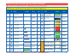
Parts List (Colors and styles may vary) Symbols and Numbers Note: If you have a more advanced model, there are additional part lists in the other project manuals. Important: If any parts are missing or damaged, DO NOT RETURN TO RETAILER. Call toll-free (800) 533-2441 or e-mail us at: help@elenco.com. Customer Service • 150 Carpenter Ave. • Wheeling, IL 60090 U.S.A. Qty. ID Name Symbol Part # Qty.
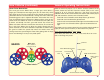
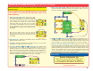
How To Use It Install six “AA” batteries (not included) into the bottom of the Rover body and one 9V•battery (not included) into the remote control unit. Install the antenna into the remote control unit by screwing it in. Antenna Remote control Front of Rover – There is also a 1-snap wire that is used as a spacer or for interconnection between different layers. A large clear plastic base grid is included with this kit to keep the circuit blocks together, it fits on top of the Rover body.
About Your Snap Circuits® Parts ! Warning to Snap Circuits® owners: Do not use parts from other Snap Circuits® sets with this kit. The Snap Rover® uses higher voltage which could damage those parts. Page 22 and our website www.snapcircuits.net has approved circuits that you can use. (Part designs are subject to change without notice). Note: If you have a more advanced Model, there is additional information in your other project manual(s).
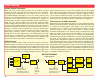
How It Works Remote Control Transmitter: When the levers in the Remote Control Unit are pushed, electrical contacts are made connecting the 9V battery power to the transmitter, indicating which commands the user wants sent to the Rover. Forwards/Backwards commands for each set of wheels and two extra functions are controlled by different levers or buttons.
How It Works (continued) General Operating Instructions Rover Drive Mechanism: Build the circuit for projects 1 or 2. Set the channel switches on the remote control unit and R/C Receiver module (RX1) to the same setting (A, B, or C). Place the Rover on a flat, open area, turn the ON/OFF switch on the remote control unit and the slide switch (S1) to ON, and extend the antenna on the Remote Control.
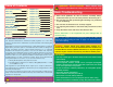
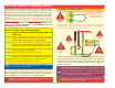
DO’s and DON’Ts of Building Circuits After building the circuits given in this booklet, you may wish to experiment on your own. Use the projects in this booklet as a guide, as many important design concepts are introduced throughout them. Every circuit will include a power source (the batteries), a resistance (which might be a resistor, motor, integrated circuit, etc.), and wiring paths between them and back.
Advanced Troubleshooting (Adult supervision recommended) Elenco® Electronics is not responsible for parts damaged due to incorrect wiring. 5. Motor Contol (U8) module: Build this circuit and turn it on, both sets of wheels should turn forward. Now shift the 1KΩ resistors (R2) to be across points A-B and C-D; the wheels should turn backwards. A B C D ROVER•REAR Now move the jumper wires to test the other two wheels, if they don’t move then the Rover body is damaged.
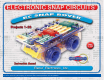
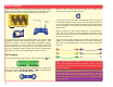
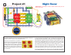
Project #1 Night Rover OBJECTIVE: To build a remote control vehicle that you can drive in the dark. ROVER•REAR + Cha nnel sw i ol unit. nt r co n remot ho e tc The Snap Circuits® Kit uses electronic blocks that snap onto a clear plastic base grid to build different circuits. These blocks have different colors and numbers on them so that you can easily identify them.
Remote Control Rover OBJECTIVE: To build a remote control vehicle. remot h on ec itc tro on l unit. Channe ls w ROVER•REAR + Project #2 Install six (6) “AA” batteries into the bottom of the Rover body and one 9V•battery into the remote control unit (batteries not included). Install the antenna into the remote control unit by screwing it in. Place the base grid on the Rover body; you may lock it into position by turning the hexagonal alignment posts (shown here), if desired.
Project #3 OBJECTIVE: To make a rotating light. Build the circuit, place the base grid centered on the Rover body, and connect the jumper wires as shown. Place the Snap Rover® in the middle of a dimly lit room and turn on the slide switch (S1). The light will shine around the room as Snap Rover® spins. ROVER•REAR + Lighthouse Project #4 Backwards Rover OBJECTIVE: To see if you can adapt to unusual controls. ROVER•REAR n remot ho ec itc unit.
Project #5 Two-Sound Rover OBJECTIVE: To build a remote control vehicle with two sound levels. l unit. Project #6 remot h on ec itc tro on Channe ls w ROVER•REAR + Build the circuit shown and turn on the slide switch (S1). Turn on the remote control unit, extend the antenna, and use the levers try to drive the Rover around. Press the left or right buttons to activiate the horn (W1); press both for a louder sound. Helpless Rover OBJECTIVE: To look at the gears.
Project #7 Morse Code + OBJECTIVE: To learn about Morse code. n remot ho ec itc ROVER•REAR unit. trol on Ch annel s w Build the circuit, connect the jumper wires, and turn on the slide switch (S1). Turn on the remote control unit and extend the antenna. Press the buttons on the remote control to generate long or short bursts of sound (from the W1 horn) or light (from the D4 LED).
Project #9 Slow Turn-Off ROVER•REAR OBJECTIVE: To show how capacitors slow things down. Build the circuit, place the base grid on the Rover body, and connect the jumper wires as shown. Turn the swtch (S1) on and the LED is on. Turn the switch off, and the LED•goes out slowly. Electricity stored in the 100μF capacitors (C4N) keeps the LED•on after the batteries have been disconnected. If you remove one of the capacitors then the LED will turn off faster, because you aren’t storing as much electricity.
Project #11 Sound & Light ROVER•REAR OBJECTIVE: To build a circuit with sound and light. + Project #12 Build the circuit, place the base grid centered on the Rover body, and connect the jumper wires as shown. Turn on the switch (S1) and electricity flows from the batteries through the circuit. The horn (W1) converts electricity into sound and the LED•(D4) converts electricity into light. The four 1KΩ resistors (R2) are connected in parallel, to act as a 250Ω resistance.
Project #13 Slow R/C Flashlight OBJECTIVE: To build a remote control light. l unit. Project #14 Channe ls w + remot h on ec itc tro on ROVER•REAR Build the circuit shown and turn on the slide switch (S1). Turn on the remote control unit, extend the antenna, and press the left button. The LED (D4) turns on and off slowly. Capacitor Battery OBJECTIVE: To show how capacitors store electrical charge. + ROVER•REAR Build the circuit shown but leave the 100μF capacitor (C4N) unconnected.
Project #15 When More Are Less ROVER•REAR OBJECTIVE: To compare types of circuits. Build the circuit and connect the jumper wires as shown. The LED•(D4) will be on but the resistor is limiting the electricity through it. Turn on the switch (S1) to place three other resistors in parallel with the first one. This increases the flow of electricity to the LED, and makes it brighter. Placing other resistors in parallel reduces the total resistance (to 250Ω here), so more are less.
Project #17 OBJECTIVE: To draw a missing component. ROVER•REAR + Pencil Buzz Build the circuit at left and connect the jumper wires to it, but leave the loose ends of the green and purple jumpers unconnected for now. There is one more part you need and you are going to draw it. Take a pencil (No. 2 lead is best but other types will also work). SHARPEN•IT, and fill in the shape below. You will get better results if you place a hard, flat surface directly beneath this page while you are drawing.
Project #19 Water Detector OBJECTIVE: To show how water conducts electricity. ROVER•REAR Build the circuit at left and connect the jumper wires to it, but leave the loose ends of the green and yellow jumpers lying on the table initially. Turn on the slide switch (S1) the LED (D4) will be dark because the air separating the jumpers has very high resistance. Touch the loose jumper ends to each other and the LED will be bright, because with a direct connection there is no resistance separating the jumpers.
One-Way Light OBJECTIVE: To show how an LED works. Build the circuit, place the base grid centered on the Rover body, and connect the jumper wires as shown. When you close the slide switch (S1), electricity flows from the batteries through the switch (S1), the LED (D4), the resistor (R1), and back to the battery. ROVER•REAR + Project #22 Conduction Detector OBJECTIVE: To make a circuit that detects the conduction of electricity in different materials.
OTHER SNAP CIRCUITS® PRODUCTS! Contact Elenco® to find out where you can purchase these products. Snap Circuits® Jr.
BONUS•CIRCUITS FOR•SNAP•CIRCUITS® OWNERS If you own Snap Circuits® Models SC-300, SC-500, or SC-750 (with 300+ experiments), then you may also build these circuits. Our website (www.snapcircuits.net) has additional circuits. DO•NOT•use parts from other Snap Circuits® kits with your Snap Rover® except in our approved circuits -•the Snap Rover® uses higher voltage which could damage those parts. ho itc n remot ec ROVER•REAR Ch annel l unit.
SCROV-10 Snap Rover® Block Layout Important: If any parts are missing or damaged, DO NOT RETURN TO RETAILER. Call toll-free (800) 533-2441 or e-mail us at: help@elenco.com. Customer Service • 150 Carpenter Ave. • Wheeling, IL 60090 U.S.A. U8 C4N C4N C1 D4 RX1 2 x2 S1 Jumper Wires R1 2 x2 R2 R2 2 x2 R2 W1 7 x1 6 x1 R2 3 x2 1 x1 5 x1 4 x1 Elenco® Electronics, Inc. 150 Carpenter Avenue • Wheeling, IL 60090 (847) 541-3800 • Fax: (847) 520-0085 • Website: www.elenco.