POWER SUPPLY KIT MODEL XP-15K Instruction & Assembly Manual ELENCO Copyright © 2012, 1991 by ELENCO® All rights reserved. ® Revised 2012 REV-P No part of this book shall be reproduced by any means; electronic, photocopying, or otherwise without written permission from the publisher.
INTRODUCTION Assembly of your XP-15K Regulated Variable Power Supply Kit will prove to be an exciting project and give much satisfaction and personal achievement. If you have experience in soldering and wiring technique, you should have no problem in the assembly of this kit. Care must be given to identifying the proper components and in good soldering habits. Above all, take your time and follow the easy step-by-step instructions. Remember, “An ounce of prevention is worth a pound of cure”.
PARTS VERIFICATION Before beginning the assembly process, familiarize yourself with the components and this instruction book. Verify that all of the parts are present. This is best done by checking off the parts in the parts list. RESISTORS CAPACITOR Carbon film SEMICONDUCTORS Diode 2kΩ Potentiometer Electrolytic (radial) LM317 Regulator LED MISCELLANEOUS Case top Transformer YD-1485 Label Lead-free solder Case bottom PC Board Screws 2.
CONSTRUCTION Introduction • Turn off iron when not in use or reduce temperature setting when using a soldering station. The most important factor in assembling your XP-15K Regulated Variable Power Supply Kit is good soldering techniques. Using the proper soldering iron is of prime importance. A small pencil type soldering iron of 25 - 40 watts is recommended. The tip of the iron must be kept clean at all times and well-tinned.
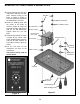
MOUNTING THE TRANSFORMER & BINDING POSTS r Peel the backing off of the label and place it onto the case top, while carefully lining up the holes as shown in Figure A. The label should fit snug within the indentation in the case. r Install the binding posts with the colors in the order as shown in Figure B. Insert the post into the hole and fasten it with the nut and lockwasher. Tighten down the nut with pliers. r Install the transformer as shown in Figure B.
ASSEMBLE COMPONENTS TO THE PC BOARD Place a check mark in the box provided next to each step to indicate that the step is completed. C4 - 220μF Electrolytic (see Figure D) D4 D3 D2 D1 D5 - 1N4001 Diode D6 - 1N4001 Diode (see Figure C) R4 - 2.2kΩ 5% 1/4W Res. (red-red-red-gold) - 1N4001 Diode 1N4001 Diode 1N4001 Diode 1N4001 Diode (see Figure C) C3 - 470μF Electrolytic (see Figure D) D8 - 1N4001 Diode D7 - 1N4001 Diode (see Figure C) R1 - 2.2kΩ 5% 1/4W Res.
WIRING Install the following wires as shown in Figure G. r Cut the blue and both yellow transformer wires so that they are 4”. Strip 1/4” insulation off the ends. Blue wire Yellow wires r Solder one of the yellow wires from the transformer to PC Board P1 and the other to P3. r Solder the blue wire from the transformer to the PC board hole P2. r Solder the red wire from the P5 to the end of the the red binding post. r Solder the red wire from the P4 to the end of the the black binding post.
LINE CORD ASSEMBLY FINAL ASSEMBLY Install the following wires as shown in Figure K. r Remove the backing from each rubber foot and place them in the locations shown in Figure L. r Cut the two black wires from the transformer to 1½”. Strip ¼” of insulation off of each wire. r Assemble the top and bottom case sections and fasten with four 2.8 x 8mm self-tapping screws as shown in Figure L. Make sure the slots on the side line up with one another. r Feed 2” of line cord into the hole of the chassis.
TESTING THE XP-15K POWER SUPPLY Testing the XP-15K Power Supply is very simple. Before applying power to the unit, be sure that all of the wiring and soldering is firm. If so, obtain a digital voltmeter. Apply power to the XP-15K and vary the voltage control knob. Set the output voltage to 15 volts and place a 75Ω 5 watt resistor across the output terminals. Again, the output should not change by more than 0.1 volts.
Each diode conducts when the voltage is positive. By adding the two outputs, the voltage presented to capacitor C1 is more complete, thus, easier to filter, as shown in Figure 2F. When used in 60 cycles AC input power, the output of a full wave rectifier will be 120 cycles. depending on the current drawn by the output load. Remember, current only flows through the diode when the anode is more positive than the cathode. Thus, current will flow in short bursts as shown in Figure 5C.
TROUBLESHOOTING GUIDE Consult your instructor or contact ELENCO® if you have any problems. DO NOT contact your place of purchase as they will not be able to help you. LED Not Lit Poor Regulation 1) Check transformer and line cord. 1) Check AC ripple at the input of the regulator. It should be less than 2.5V. 2) Check for 20VDC at the cathode of D1. 2) If ripple is higher, check diodes D1, D3, and the filter of capacitor C1. 3) LED in backwards or defective.
SCHEMATIC DIAGRAM REV-A Answers: 1. B, 2. B, 3. C, 4. D, 5. C, 6. D, 7. D, 8. C, 9. D, 10. A ELENCO® 150 Carpenter Avenue • Wheeling, IL 60090 (847) 541-3800 • Website: www.elenco.com • e-mail: elenco@elenco.