
Specifications


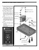


Figure F
-5-
D4 - 1N4001 Diode
D3 - 1N4001 Diode
D2 - 1N4001 Diode
D1 - 1N4001 Diode
(see Figure C)
D8 - 1N4001 Diode
D7 - 1N4001 Diode
(see Figure C)
C1 - 2,200μF Electrolytic Cap.
(see Figure D)
R2 - 150Ω 5% 1/4W Res.
(brown-green-brown-gold)
U1 - LM317 Regulator
(see Figure E)
ASSEMBLE COMPONENTS TO THE PC BOARD
Place a check mark in the box provided next to each step to indicate that the step is completed.
C4 - 220μF Electrolytic
(see Figure D)
D5 - 1N4001 Diode
D6 - 1N4001 Diode
(see Figure C)
R4 - 2.2kΩ 5% 1/4W Res.
(red-red-red-gold)
C3 - 470μF Electrolytic
(see Figure D)
R1 - 2.2kΩ 5% 1/4W Res.
(red-red-red-gold)
C2 - 4.7μF Electrolytic
(see Figure D)
P4 - 3” Red wire
P5 - 3” Red wire
Cut two 3” wires from the cut-
off red transformer wires and
strip 1/4” of insulation off of
each side.
Figure D
These capacitors are polarized. Be sure
to mount them with the “+” lead in the
correct hole as marked on the PC
board. Also, the negative lead of a radial
electrolytic is shorter than the positive
one.
Warning: If the capacitor is connected
with incorrect polarity it may heat up and
either leak or cause the capacitor to
explode.
Figure C
Diodes have polarity. Be sure to
mount them with the band going
in the same direction as marked
on the PC board.
Band
Polarity
marking
(–) (+)
Figure E
Mount the regulator as shown, with the metal backing in
the same direction as the marking on the PC board. Attach
the heat sink using a 4-40 x ¼” screw and 4-40 nut.
4-40 x ¼”
Screw
4-40 Nut
Heat sink
Metal backing
PC board marking
1/4”
D9 - LED
r Mount the
LED to the
copper side
of the PC
board, spaced 3/8” off the
board, with the flat side in
the same direction as
shown in Figure F.
R3 - 2kΩ Potentiometer
r Mount the potentiometer
to the copper side of the
PC board as shown in
Figure F. Insert the the
pins through the holes so
the body sits flat against
the PC board, then solder
in place.
2kΩ Potentiometer
LED
Flat side
3/8”
Flat side
Copper side of PC board
Long lead (+)
Short lead (–)
(–) (+)
Flat
side