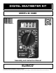
DIGITAL MULTIMETER KIT MODEL M-1008K Assembly and Instruction Manual ELENCO ® Copyright © 2012 by ELENCO® All rights reserved. No part of this book shall be reproduced by any means; electronic, photocopying, or otherwise without written permission from the publisher.
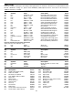
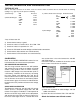
PARTS LIST If you are a student, and any parts are missing or damaged, please see instructor or bookstore. If you purchased this meter kit from a distributor, catalog, etc., please contact ELENCO® (address/phone/e-mail is at the back of this manual) for additional assistance, if needed. RESISTORS (Parts mounted on card) Qty. Symbol Value Color Code r 1 R7 0.99Ω 0.5% 1/4W r 1 R8 9Ω 0.5% 1/4W r 1 R19 10Ω 1% 1/4W r 1 R18 100Ω 1% 1/4W r 1 R1 100Ω 0.
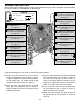
PARTS IDENTIFICATION RESISTORS MISCELLANEOUS Shunt wire Battery snap Potentiometer Carbon film Zebra Liquid crystal display (LCD) CAPACITORS C2 Mylar Disc Electrolytic SEMICONDUCTORS Buzzer with wires Fuse holder clip Zebra frame 2.0mm x 6mm Screws Input socket Diode Transistor Selector knob Transistor socket 2.
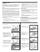
CONSTRUCTION Introduction • Tips should be cleaned frequently to remove oxidation before it becomes impossible to remove. Use Dry Tip Cleaner (Elenco® #SH-1025) or Tip Cleaner (Elenco® #TTC1). The most important factor in assembling your M-1008K Digital Multimeter Kit is good soldering techniques. Using the proper soldering iron is of prime importance. A small pencil type soldering iron of 25 - 40 watts is recommended. The tip of the iron must be kept clean at all times and well tinned.
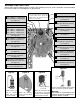
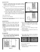
ASSEMBLY INSTRUCTIONS Identify and install the following parts as shown. After soldering each part, mark a check þ in the box provided. Be sure that solder has not bridged to an adjacent pad. R14 - 100kΩ 1% 1/4W Resistor (brown-black-black-orange-brown) (see Figure A) NOTE: The 7106 IC1 is already installed on the PC board. This type of installation is called C.O.B. (chip on board). The LM358 U2 IC is also mounted and uses a surface mount package.
ASSEMBLY INSTRUCTIONS Identify and install the following parts as shown. After soldering each part, mark a check þ in the box provided. Be sure that solder has not bridged to an adjacent pad. Figure E R26 - 47kΩ 1% 1/4W Resistor R27 - 47kΩ 1% 1/4W Resistor (yellow-violet-black-red-brown) (see Figure A) Stand diode on end. Mount with band as shown on the top legend.
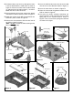
r Insert the LCD into the frame (the tab on the LCD must be in the same direction shown in Figure J). r Feed the battery snap wires up through the holes in the PC board from the solder side as shown in Figure F. Insert the red wire into the hole marked (+) and black wire into hole marked (–) as shown. Solder the wires to the PC board. r Insert the zebra frame as shown in Figure K. r Place the zebra onto the grooved surface of the LCD as shown in Figure K.
r Put the ball bearings into two opposite indents in the case top as shown in Figure M. r Place the PC board over the selector knob. Be sure that the 8-pin socket slides into its hole. Then fasten the PC board with five 6mm screws as shown. r Place the six slide contacts on the selector knobs as shown. r Insert the 200mA, 250V fuse into the fuse clips. r Place the selector knob into the case top so that the springs fit over the ball bearings as shown.
TESTING, CALIBRATION, AND TROUBLESHOOTING TESTING OF LCD With no test leads connected to the meter, move the selector switch around the dial. You should obtain the following readings. A (–) sign may also be present or blinking. 1) ACV Range: 600 200 2) DCA,10A Ranges: 200μ 2,000μ 20m 200m 10A HV 0 0 0 0 0.0 3) Ohms, Diode and hFE Ranges: B indicates blank. hFE 000 Diode “ ”“ ” 1BBB 200 1 B B.B 0 0.0 000 0.0 0 0 0.0 0.0 0 200 2,000 20k 200k 2,000k 4) DCV Range: 1 B B.B 1BBB 1 B.B B 1 B B.
DC VOLTS TEST 123 1) If you have a variable power supply, set the supply to about the midpoint of each of the DCV ranges and compare the kit meter reading to a meter known accuracy. 10A DC 2) If you do not have a variable power supply, make the following two tests: VΩmA 1kΩ COM 9V a) Set the range switch to 2V and measure the voltage across the 100Ω resistor of Figure O. You should get about 820mV. Compare the reading to a meter of known accuracy.
2) Read the hFE of the transistor. The hFE of transistors varies over a wide range, but you will probably get a reading between 100 and 300. RESISTANCE / DIODE TEST 1) Measure a resistor of about half of the full scale value of each resistance range. Compare the kit meter readings to those from a meter of known accuracy. If this check fails: a) Check the value and soldering of resistors R19-21. 2) Measure the voltage drop of a good silicon diode. You should read about 700mV.
THEORY OF OPERATION A block diagram of the M-1008K is shown in Figure 1. Operation centers around a custom LSI chip. This chip contains a dual slope A/D (analog to digital) converter, display latches, seven segment decoder and display drivers. A block diagram of the IC functions is shown in Figure 1. The input voltage or current signals are conditioned by the selector switches to produce an output DC voltage with a magnitude between 0 and 199mV.
The integrate period begins at the end of the autozero period. As the period begins, the AZ switch opens and the INTEG switch closes. This applies the unknown input voltage to the input of the A/D converter. The voltage is buffered and passed on to the integrator to determine the charge rate (slope) on the INTEG capacitor. At the end of the fixed integrate period, the capacitor is charged to a level proportional to the unknown input voltage.
a f a b g b e c d BACKPLANE 28 LCD PHASE DRIVER 7 Segment Decode 7 Segment Decode TYPICAL SEGMENT OUTPUT V+ 7 Segment Decode 200 0.5mA LATCH Segment Output 2mA Thousand Tens Hundreds Units Internal Digital Ground To Switch Drivers From Comparator Output V+ CLOCK 6.2V LOGIC CONTROL –4 * 3 TEST Internal Digital Ground 1V 500Ω * Three inverters. One inverter shown for clarity. 8 7 6 OSC 3 OSC 2 OSC 1 CREF CREF+ 42 V+ 44 43 A-Z & Z1 41 A-Z & Z1 1 + 2.
DC VOLTAGE MEASUREMENT 200mV Figure 4 shows a simplified diagram of the DC voltage measurement function. The input voltage divider resistors add up to 1 megaohm. Each step down divides the voltage by a factor of ten. The divider output must be within the range –0.199 to +0.199 volts or the overload indicator will function. The overload indication consists of a 1 in the most significant digit and blanks in the remaining digits.
CONTINUITY MEASUREMENT Figure 8 shows a diagram of the continuity measurement function. The circuit uses two opamps and a piezoelectric buzzer. When the leads are connected across a circuit and the resistance less than 20Ω the circuit oscillates and the buzzer sounds. Figure 8 hFE MEASUREMENT V+ Figure 9 shows a simplified diagram of the hFE measurement function. Internal circuits in the 7106 IC maintain the COMMON line at 2.8 volts below V+.
METER OPERATION PRECAUTIONS AND PREPARATIONS FOR MEASUREMENT 1) Be sure the battery is connected to the battery snap and correctly placed in the battery compartment. 5) Operate the instrument only in temperatures between 0 and 50°C and in less than 80% RH. 6) Pay careful attention to the maximum rated voltage of each range and terminal. 2) Before connecting the test leads to the circuit, be sure the range switch is set to the correct position. 7) When finished making measurements, set the switch to OFF.
DIODE CHECK hFE MEASUREMENTS 1) Connect the black test lead to the “COM” terminal. 1) Set the range switch to hFE and insert the test transistor into the appropriate NPN or PNP holes in the transistor socket. 2) Connect the red test lead to the “VΩmA” terminal. 3) If the diode being measured is connected to a circuit, turn off all power to the circuit and discharge all capacitors. 4) Set the range switch to “ 2) Read the hFE of the transistor. ”.
-18Answers to Quiz: 1. C, 2. D, 3. B, 4. A, 5. D, 6. A, 7. B, 8. C, 9. B, 10.
ELENCO® 150 Carpenter Avenue Wheeling, IL 60090 (847) 541-3800 Website: www.elenco.com e-mail: elenco@elenco.