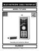
MULTI-NETWORK CABLE TESTER KIT MODEL TCT-255K Assembly and Instruction Manual ELENCO ® Copyright © 2013, 2001 by ELENCO® All rights reserved. REV-D No part of this book shall be reproduced by any means; electronic, photocopying, or otherwise without written permission from the publisher.
INTRODUCTION The TCT-255 Cable Tester is a convenient instrument for testing different unshielded wiring schemed communication cable with RJ-11 and RJ45 connectors and coax cable. This tester can be used for testing cables before and/or after they are installed. The tester offers easy operation by having to push only one button. Testing status is indicated by multiple LEDs and an auto power-off function maximizes battery life.
IDENTIFYING RESISTOR VALUES Use the following information as a guide in properly identifying the value of resistors. BAND 1 1st Digit Color Black Brown Red Orange Yellow Green Blue Violet Gray White BAND 2 2nd Digit Digit 0 1 2 3 4 5 6 7 8 9 Color Black Brown Red Orange Yellow Green Blue Violet Gray White Multiplier Digit 0 1 2 3 4 5 6 7 8 9 Color Black Brown Red Orange Yellow Green Blue Silver Gold Resistance Tolerance Multiplier 1 10 100 1,000 10,000 100,000 1,000,000 0.01 0.
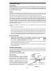
CONSTRUCTION Introduction The most important factor in assembling your TCT-255 Multi-Netwok Cable Tester Kit is good soldering techniques. Using the proper soldering iron is of prime importance. A small pencil type soldering iron of 25 - 40 watts is recommended. The tip of the iron must be kept clean at all times and well tinned. Solder For many years leaded solder was the most common type of solder used by the electronics industry, but it is now being replaced by lead-free solder for health reasons.
A poorly soldered joint can greatly affect small current flow in circuits and can cause equipment failure. You can damage a PC board or a component with too much heat or cause a cold solder joint with insufficient heat. Sloppy soldering can cause bridges between two adjacent foils preventing the circuit from functioning. What Good Soldering Looks Like Types of Poor Soldering Connections A good solder connection should be bright, shiny, smooth, and uniformly flowed over all surfaces. Soldering Iron 1.
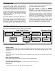
SECTION A Power Supply PARTS LIST - SECTION A RESISTORS Qty. r 2 r 1 r 1 r 1 Symbol R12, R17 R16 R15 R9 Description 1kΩ 5% 1/4W 5.6kΩ 5% 1/4W 12kΩ 5% 1/4W 3.3MΩ 5% 1/4W Color Code brown-black-red-gold green-blue-red-gold brown-red-orange-gold orange-orange-green-gold Part # 141000 145600 151200 173300 CAPACITORS Qty. r 1 Symbol C2 Value 22µF Description Electrolytic Radial Part # 272244 SEMICONDUCTORS Qty. r 1 r 1* r 1 r 2 r 1 r 1 r 1 Symbol D17 Qty.
ASSEMBLE THE FOLLOWING COMPONENTS TO THE PC BOARD In all of the following steps the components must be installed on the top legend side of the PC board. The board is turned to solder the component leads on the foil side. SW1 - Push Button Switch (see Figure F) R17 - 1kΩ 5% 1/4W Resistor (brown-black-red-gold) (see Figure A) R16 - 5.6kΩ 5% 1/4W Resistor (green-blue-red-gold) (see Figure A) D19 - LED Red Tubing Spacer (see Figure B) C2 - 22µF Electrolytic (see Figure G) R9 - 3.
SECTION A - POWER SUPPLY When the SW1 (test button) is pushed, capacitor C2 (see schematic diagram, Figure 1) is charged to the battery voltage. Transistor Q1 turns on and all of the circuits in the tester are powered. If you don’t push SW1, capacitor C2 begins discharging. When the voltage on C2 is less than 0.7V, transistor Q1 and the power turn off after 30-50 seconds. When the voltage of the battery is less than 7.5V, transistors Q2 and Q3 turn on and LED D19 (Low Battery) lights.
SECTION B Oscillator PARTS LIST - SECTION B RESISTORS Qty. r 1 r 1 Symbol R13 R14 Description 18kΩ 5% 1/4W 100kΩ 5% 1/4W Color Code brown-gray-orange-gold brown-black-yellow-gold Part # 151800 161000 CAPACITORS Qty. r 1 Symbol C3 Value 1µF Qty. r 1 Symbol U5 Value 555 Qty.
SECTION B - OSCILLATOR The oscillator section consists of a 555 timing circuit, resistors R13, R14, and capacitor C3. The 555 IC is configured as an astable or free-running oscillator. The values of the resistor R14 and capacitor C3 set the output frequency at 8Hz. The IC will produce a continuous 8Hz square wave from pin 3 as long as it is powered. To Switches Figure 4 TESTING r 1. Connect the battery to the battery snap. r 2.
SECTION C Step Pulses with Counter PARTS LIST - SECTION C RESISTORS Qty. r 1 r 1 Symbol R11 R10 Description 680kΩ 5% 1/4W 1.2MΩ 5% 1/4W Color Code blue-gray-yellow-gold brown-red-green-gold Part # 166800 171200 CAPACITORS Qty. r 1 Symbol C1 Value .001µF Qty. r 1 Symbol U1 Value 4017 Qty. r 1 Symbol U1 Description Socket IC 16-pin Description Discap (102 or .
SECTION C - STEP PULSES WITH COUNTER In this section, a 4017 counter IC and a 40106 inverter IC are used to control eight electronic switches. A short positive pulse must be generated and applied to the clock input of the 4017 IC whenever switch SW1 is depressed. This is done by wiring three inverters in series. When switch SW1 is depressed, the voltage at pin 1 of the 40106 is pulled to ground. This low condition is then inverted three times to produce a positive pulse to the CLK pin of the 4017.
SECTION D Switches and LED Indicator PARTS LIST - SECTION D RESISTORS Qty. r 8 Symbol R1-R8 Description 200Ω 5% 1/4W Color Code red-black-brown-gold Qty. r 1 Symbol C4 Value 470µF 16V Description Electrolytic Radial Part # 132000 CAPACITORS Part # 284744 SEMICONDUCTORS Qty. Symbol r 16 D1-D16 r 2 U2, U3 Value Description LED Red Integrated Circuit (IC) Quad Analog Switch 74HC4066 Part # 350003 394066 MISCELLANEOUS Qty.
ASSEMBLE THE FOLLOWING COMPONENTS TO THE PC BOARD In all of the following steps the components must be installed on the top legend side of the PC board. The board is turned to solder the component leads on the foil side.
ASSEMBLE THE FOLLOWING COMPONENTS TO THE PC BOARD (cont.) Spacer (see Figure M) D9 - LED D10 - LED D11 - LED D12 - LED D13 - LED D14 - LED D15 - LED D16 - LED (see Figure N) Figure M Figure N Mount the spacer to the PC board as shown. Mount the LEDs onto the spacer as shown. Note the flat side of the LED in relation to the marking on the PC board. Solder and cut off the excess leads.
SECTION D - SWITCHES AND LED INDICATOR In this section, two quad analog switches (74HC4066) and 16 LEDs are used to indicate which pins are being tested and the type of cable. Figure 8 shows the logic diagram for each switch. Each switch contains an input, output and a control pin. The inputs are connected to the oscillator section and the outputs to two LEDs and connector. The control pins connect to the outputs of the 4017 IC (see Figure 10).
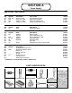
SECTION E Terminator PARTS LIST - SECTION E SEMICONDUCTORS Qty r 4 Symbol D1-D4 Value 1N4148 Description Diode Qty r 1 r 1 r 1 Symbol Description PC Board Terminator LD-100 F-Connector Modular Jack RJ-45 Part # 314148 MISCELLANEOUS J2 J1 Part # 510005 590500 621028 PARTS IDENTIFICATION F-Connector Modular Jack Diode PC Board ASSEMBLE THE FOLLOWING COMPONENTS TO THE PC BOARD In all of the following steps the components must be installed on the top legend side of the PC board.
SECTION E - TERMINATOR The terminator uses four diodes to identify the polarity of the input signals. The diodes are placed in series with wires 1-8, 2-7, 3-6, and 4-5 (see Figure 11). Figure 11 SECTION F Assemble Telecom Cables PARTS LIST - SECTION F MISCELLANEOUS Qty.
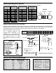
ASSEMBLE THE TELECOM CABLES For testing and troubleshooting the tester, you need to assemble straight and cross-pinning cables. For cutting, stripping, and crimping, use a standard tool for RJ-45 plugs (flat cable). ELENCO® has modular crimping tools Models ST-500 and HT-568. Straight Cable (BL) 1 (OR)2 (BK) 3 (R) 4 (G) 5 (Y) 6 (BN) 7 (S) 8 1 2 3 4 5 6 7 8 Cross-Pinning Cable (BL) 1 (OR)2 (BK) 3 (R) 4 (G) 5 (Y) 6 (BN) 7 (S) 8 1 2 3 4 5 6 7 8 Note the orientation of the RJ-45 plug for each cable.
SECTION G Final Test and Assembly PARTS LIST - SECTION G MISCELLANEOUS Qty. r 2 r 1 r 1 r 1* r 1 r 1* r 1 r 1 r 2 r 4 r 1 r 1* r 1* r 1 Symbol Description F to BNC Adapter Button Cap Case Top Tester Case Top Terminator Case Bottom Tester Case Bottom Terminator Cover Battery Velcro Hook and Loop Set Screw 2.6 x 8mm Thread Cutting Phillips Pan Head Screw 3 x 12mm Thread Cutting Phillips Flat Head Screw M3 x 10mm Machine Phillips Flat Head Screw 2.
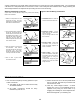
SECTION G - FINAL TEST Straight Cable Cross-Pinning Cable r 1. Connect one end of the straight cable to the modular jack on the PC board of the terminator and the second end to the PC board of the cable tester as shown in Figure 16a. r 2. Push switch SW1 until the two vertical LEDs D1 and D9 are blinking alternately and LED D16 should be blinking too. r 1. Remove the straight cable and connect the cross-pinning cable to the modular jacks on the PC boards of the tester and terminator. r 2.
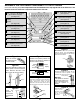
SECTION G - FINAL ASSEMBLY OF TESTER r Push the button cap onto the switch as shown in Figure O. r Mount the bottom case to the front case, as shown in Figure Q, using four 3 x 12mm flat phillips screws. Be sure that the battery snap is through the battery compartment hole as shown. r Mount the PC board to the top case, as shown in Figure P, with two 2.6 x 8mm phillips screws. Note: The button cap should be centered in the top case hole. Make sure that the Lo Batt LED goes through the hole in the case.
FINAL ASSEMBLY OF TESTER (cont.) r Insert the M3 x 10mm machine phillips screw into the battery cover hole, as shown in Figure S, and tighten. r Peel the backing off of the label and stick it onto the front case as shown in Figure T. Use the hole in the middle to line up the label. Note: Be very careful when applying this label.
FINAL ASSEMBLY (cont.) r Peel off the two backings, and attach the two velcro pieces onto the terminator and the tester in the location shown in Figure W. Velcro Pieces Figure W SPECIFICATIONS CATEGORY OF CABLE ENVIRONMENTAL CONDITIONS • Unshielded communication cable with RJ-11 and RJ-45 connectors. • Operating Conditions: 0OC - 45OC / 32OF - 113OF 70% RH max. • Ethernet 10 Base-T, Token Ring, EIA/TIA-568A/B, AT&T 258A, and USOC. • Storage Conditions: -10OC - 50OC / 14OF - 122OF 80% RH max.
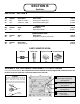
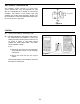
OPERATION INSTRUCTIONS 1. Connect one end of the cable to be tested to the terminator and the other end to the cable tester as shown in Figure 17. 3. Push the TEST button again and read the result for the next pair. 4. For testing coax cable, use the middle LEDs (boxed in as coax on the unit). 2. Push the TEST (power) button and read the result. Good Pair: Two vertical and one single blinking LEDs. The location of the single LED indicates a straight or cross-pinning for the pair. 5.
WIRING SCHEMES Ethernet 10Base-T EIA/TIA-568A EIA/TIA-568B AT&T 258A 8-Position Token Ring USOC USOC (Prs. 1,2 & 3) RJ-11 (4-Wire) Straight-Pinning (Y) (G) (R) (BL) RJ-11 (4-Wire) Cross-Pinning 1 2 3 4 1 2 3 4 (Y) (G) (R) (BL) 1 2 3 4 1 2 3 4 NOTE: Cross-Pinning is for typical telephone use.
MAINTENANCE GENERAL MAINTENANCE 3. Carefully remove the old battery and replace with a new battery. To clean, wipe the case with a damp cloth and detergent (do not use abrasives or solvents). 4. Reinsert the battery into the case, dressing the battery leads so that they will not be pinched between the case and the battery cover. When the Lo Batt. LED lights up, you need to replace the battery. The terminator does not use a battery. 5. Reinstall the battery cover and screw.
ELENCO® 150 Carpenter Avenue Wheeling, IL 60090 (847) 541-3800 www.elenco.com email: elenco@elenco.