DIGITAL / ANALOG TRAINER MODEL XK-700K A COMPLETE MINI-LAB FOR BUILDING, TESTING AND PROTOTYPING ANALOG AND DIGITAL CIRCUITS Tools and meter shown not included. Assembly & Instruction Manual ELENCO ® Copyright © 2013, 1996 by ELENCO® Electronics, Inc. All rights reserved. Revised 2012 REV-G No part of this book shall be reproduced by any means; electronic, photocopying, or otherwise without written permission from the publisher.
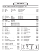
PS-700-B XK-700K POWER SUPPLY KIT (PS-700-B) PARTS LIST Qty. r r r r r RESISTORS Description R1, R2 R50, R51 VR3 VR1, VR2 VR4 120W 5% 1/4W 1.2kW 5% 1/2W 1kW 2kW 100kW 3 5 4 1 C7-C9 C12, C14-C17 C1, C2, C4, C5 C3 .1mF 100V 100mF 1000mF 35V 2200mF 25V 19 1 1 1 1 1 D1-D15, D26-D29 1N4001 Diode U1 LM317 Integrated circuit (IC) U5 LM337 Integrated circuit (IC) U3 LM7805 Integrated circuit (IC) U2 LM7812 Integrated circuit (IC) U4 LM7912 Integrated circuit (IC) Qty. r r r r r r Value 2 2 1 2 1 Qty.
PARTS VERIFICATION Before beginning the assembly process, first familiarize yourself with the components and this instruction book. Verify that all parts are present. This is done best by checking off each item in the parts list.
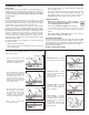
CONSTRUCTION Introduction • Turn off iron when not in use or reduce temperature setting when using a soldering station. The most important factor in assembling your XK-700K Digital/Analog Trainer Kit is good soldering techniques. Using the proper soldering iron is of prime importance. A small pencil type soldering iron of 25 watts is recommended. The tip of the iron must be kept clean at all times and well-tinned.
INTRODUCTION The XK-700K Digital/Analog Trainer is divided into four separate kits: BB-700-A, PS-700-B, AN-700-C and DG700D. Each bag of parts is clearly identified. Open only the kit called for in your procedure. DO NOT open any other bag at this time. The first kit is the BB-700-A which contains only the breadboard. The breadboard will be assembled to the front panel of the trainer during the assembly of the PS-700-B Power Supply. Read your instructions carefully.
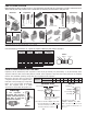
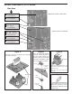
INSTALL COMPONENTS TO PC BOARD Start Here Bottom left corner of PC board S1 - 5-pin connector (see Figure A) L-bracket (see Figure B) VR4 - 100kW pot VR3 - 1kW pot (see Figure C) Top left corner of PC board S3 - 3-pin connector S2 - 3-pin connector (see Figure A) L-bracket (see Figure B) C8 - 0.1mF mylar (104) (see Figure D) Figure A Mount the connector as shown and solder the pins of the connector. Figure B Note: One side of the bracket is longer. Mount this side to the PC board.
INSTALL COMPONENTS TO PC BOARD Bottom left corner of PC board Start Here R1 - 120W 5% 1/4W resistor (brown-red-brown-gold) J28 - Jumper wire (see Figure F) J6 - Jumper wire (see Figure F) D12 - 1N4001 diode D11 - 1N4001 diode (see Figure G) C14 - 100mF 25V lytic C17 - 100mF 25V lytic (see Figure E) R2 - 120W 5% 1/4W resistor (brown-red-brown-gold) J2 - Jumper wire (see Figure F) J3 - Jumper wire (see Figure F) Figure E These capacitors are polarized.
INSTALL COMPONENTS TO PC BOARD Start Here VR1 - 2kW pot VR2 - 2kW pot (see Figure H) B1 B2 B3 B4 - 4-pin bredblox 4-pin bredblox 4-pin bredblox 4-pin bredblox (see Figure I) C12 - 100mF 25V lytic (see Figure E) J26 - Jumper wire J7 - Jumper wire (see Figure F) D15 - 1N4001 diode D14 - 1N4001 diode D13 - 1N4001 diode (see Figure G) C15 - 100mF 25V lytic C16 - 100mF 25V lytic (see Figure E) J4 - Jumper wire J1 - Jumper wire (see Figure F) R50 - 1.2kW 1/2W resistor R51 - 1.
INSTALL COMPONENTS TO PC BOARD Bottom right corner of PC board Start Here C2 C4 C1 C5 - 1,000mF 35V - 1,000mF 35V - 1,000mF 35V - 1,000mF 35V (see Figure J) lytic lytic lytic lytic D1 - 1N4001 diode D2 - 1N4001 diode D3 - 1N4001 diode D4 - 1N4001 diode D5 - 1N4001 diode D6 - 1N4001 diode D7 - 1N4001 diode D8 - 1N4001 diode D9 - 1N4001 diode D10 - 1N4001 diode (see Figure K) Figure J These lytics must be mounted horizontal to the PC board.
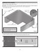
MOUNTING THE PC BOARD Note: The holes in the two side panels have been punched differently. Be sure that you have the correct side panel when mounting them to the PC board. IMPORTANT: Push the PC board up as far as possible before tightening the screws, as shown in Figure O. r Mount the PC board to the side panels with four 4-40 x 1/4” screws (see Figure N). Do not tighten the screws.
MOUNT COMPONENTS TO THE SIDE PANELS Mount U1, U3 and U5 to the left side panel as shown in Figure Q. Insert the pins of each IC into the holes of the PC board. Then, with the hardware shown in Figure P, attach each IC to the side panel. Solder the pins of the ICs to the PC board.
Mount U2 and U4 to the right side panel as shown in Figure S. Insert the pins of each IC into the holes in the PC board. Then, with the hardware shown in Figure R, attach each IC to the side panel. Solder the pins of the ICs to the PC board. r U4 - LM7912 Figure R r Transformer mounted * Take a small amount of silicone grease from the packet and apply it with a toothpick onto the back of the ICs. Note: Make sure that the transformer does not touch U4.
HOW TO INSTALL CONNECTORS ONTO TRANSFORMER WIRES A connector will be placed onto the primary wires of the transformer. This will allow you to remove the top panel from the trainer. Follow the procedures below. r Cut a six inch length off of each black primary wire. r Strip the insulation off of each end of the six inch wires to expose 1/4” of bare wire. r Place one wire onto the female pin and crimp the outer crimp tabs with pliers over the insulation as shown in Figure 1A.
MOUNT COMPONENTS TO PANEL r Push the illuminated switch into the hole in the top panel with the lugs as shown in Figure V. r Install the fuse holder with the side lug in the position shown in Figure V. Fasten the fuse holder in place with the nut as shown in Figure V. Unscrew the cap and insert the fuse into the holder. r There is a raised area on the back side of the top panel.
WIRE SWITCH AND FUSE HOLDER (see Figure Z) Line Cord r Slide the line cord through the frame as shown. r Spread the three line cord wires apart 6” from the end. r Mount the solder lug to the side panel using a 6-32 x 5/16” screw and 6-32 nut. Fuse r Strip the insulation off of both ends of the 6” red wire to expose 1/4” of bare wire. Pass the wire through the 1/2” diameter shrink tubing. Attach one end to the side lug on the fuse holder and then solder into place.
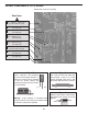
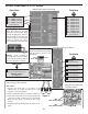
RESISTANCE ANALYSIS OF POWER SUPPLY Static testing of the power supply circuits. Do not plug the power supply into the 120VAC power supply source until all resistance readings check out. The values given below are approximate. See Figure AA for locations of testing points.
Locations for Testing Points 29 3 16 24 15 28 23 LM-7912 ••• LM-7812 Plug of line cord 1 2 ••• 9 8 7 14 13 12 11 10 4 6 5 On test points 4 - 14 use the leads of the diodes.
VOLTAGE ANALYSIS OF POWER SUPPLY Proceed with the voltage analysis only if the resistance readings were satisfactory. Place the top panel on the unit. If any capacitors are inserted backwards, the panel will shield you if they explode. Make sure that the ON/OFF switch is in the OFF position. Plug the line cord into the 120VAC power source. Turn the unit on and let it sit for a few minutes. Turn OFF the ON/OFF switch and remove the top panel, placing it along the left side of the trainer.
POWER SUPPLY TESTING Plug the trainer into a 120VAC outlet and switch to the “ON” position (the power switch should light). With a digital voltmeter, measure the voltage outputs at the power blocks. The +12V should measure between 11.4 and 12.6 volts. The 5V supply should read between 4.75 and 5.25 volts. The –12V supply should read between –11.4 and 12.6 volts. work, but use it only for a few seconds). The output of the 12V supply should not change more than 0.20 volts.
PROBLEM POSSIBLE CAUSE No or low voltage at negative variable output with load. 1. Check to see if capacitor C5 1000mF is inserted in the correct polarity. 2. Check ripple on pin 2 of U5. 6VP-P max. A. Capacitor C5 and/or diodes D8, D10 defective. No voltage at negative variable output. No +12V at output. No +12V at output with load. No –12V at output. No –12V at output with load. No +5VDC at output No +5VDC at output with load. 1. Measure for an AC voltage of 18VAC at cathode of D8, D10. A.
FINAL ASSEMBLY If you are immediately going to build the remaining sections, do not continue with the instructions on this page and proceed to page 22. r Fasten the front panel in place with four #6 x 3/8” thread cutting screws, as shown in Figure BB. Knobs r Fasten the PC board to the spacer on the front panel with a fiber washer and a 4-40 x 1/4” screw (from Power Supply Section) from the foil side of the PC board, in the location shown in Figure CC.
INSTALL COMPLETED UNIT INTO CASE r Place the strain relief onto the line cord as shown in Figure FF. r Squeeze the two sections together with pliers as shown in Figure GG. Then, insert the strain relief into the hole. r Lay the trainer inside of the case as shown in Figure HH. r Align the holes in the bottom case with those in the trainer and secure it into place with four #6 x 1/2” AB screws and four #6 washer as shown in Figure II.
CIRCUIT DESCRIPTION The power supply features two variable output voltages and three fixed 12V, –12V and 5V variable output voltages are 0V to 20V and 0 to –20V at up to 1 ampere maximum current. All supplies are regulated to better than 0.2V when going from no load to full load. Varying the input AC voltage from 105 to 135V will have practically no effect on the output voltages. This is because of the specially designed ICs used in the XK-700 Digital/Analog Trainer.
In practice, the current through the diodes is not as shown in Figure 2C. Because capacitor C1 has a charge after the first cycle, the diode will not conduct until the positive AC voltage exceeds the positive charge in the capacitor. Figure 5 shows a better picture of what the current flow looks like assuming no loss in the diode. It takes a few cycles for the voltage to build up on the capacitor. This depends on the resistance of the winding and the diode.
SCHEMATIC DIAGRAM - POWER SUPPLY SECTION -24-
QUIZ - POWER SUPPLY SECTION INSTRUCTIONS - Complete the following examination and check your answers carefully. 1. AC voltage is supplied to the rectifier stages by the . . . r A. step-up transformer. r B. step-down transformer. r C. 1 to 1 transformer. r D. AC to DC transformer. 2. The secondary windings of the transformer are . . . r A. 90O out of phase. r B. 180O out of phase. r C. 270O out of phase. r D. 320O out of phase. 3. Diodes allow current to flow . . . r A.
AN-700-C XK-700 ANALOG KIT (AN-700-C) PARTS LIST Qty. r2 r1 r2 r1 r1 r2 r1 r1 r1 r1 r3 r1 r1 r1 r1 r2 Symbol R14, R44 R5 R46, R47 R12 R49 R7, R11 R3 R13 R10 R6 R4, R45, R48 R9 R8 VR8 VR5 VR6, VR7 Value 100W 5% 1/4W 200W 5% 1/4W 330W 5% 1/4W 1kW 5% 1/4W 2kW 5% 1/4W 4.7kW 5% 1/4W 6.8kW 5% 1/4W 8.2kW 5% 1/4W 10kW 5% 1/4W 12kW 5% 1/4W 22kW 5% 1/4W 47kW 5% 1/4W 51kW 5% 1/4W 100kW Trim Pot 10kW Pot 100kW Pot Qty. r2 r2 r1 r1 r1 Symbol D16, D17 Q1, Q3 Q2 U10 U6 Value 1N4148 2N3904 2N3906 LM318 XR2206 Qty.
INTRODUCTION - ANALOG SECTION The Analog Section of your trainer contains a complete function generator capable of producing sine, square, and triangle waveforms. The frequency of this generator can be continuously varied from 1 hertz to over 100,000 hertz in five steps: 10, 100, 1k, 10k, and 100k. A fine frequency control makes selection of any frequency in between easy. The amplitude of the waveforms are adjustable from 015Vpp.
INSTALL COMPONENTS TO PC BOARD Start Here Continue J9 - Jumper Wire (see Figure A) R5 - 200W 5% 1/4W Resistor (red-black-brown-gold) J10 - Jumper Wire J25 - Jumper Wire (see Figure A) R3 - 6.8kW 5% 1/4W Resistor (blue-gray-red-gold) C25 - .
INSTALL COMPONENTS TO PC BOARD Continue Start Here R48 - 22kW 5% 1/4W Resistor (red-red-orange-gold) B6 - 4-pin Bredblox (see Figure F) D16 - 1N4148 Diode (see Figure G) Q1 - 2N3904 Transistor (see Figure C) R14 - 100W 5% 1/4W Resistor (brown-black-brown-gold) R47 - 330W 5% 1/4W Resistor (orange-orange-brown-gold) R12 - 1kW 5% 1/4W Resistor (brown-black-red-gold) R45 - 22kW 5% 1/4W Resistor (red-red-orange-gold) B5 - 4-pin Bredblox (see Figure F) R46 - 330W 5% 1/4W Resistor (orange-orange-brown-
INSTALL COMPONENTS TO PC BOARD Start Here J18 - Jumper Wire (see Figure A) Figure H Cut off tab Mount down flush with PC board. The value may be marked on the back side of pot. Cut off excess lead length after soldering. R13 - 8.2kW 5% 1/4W Resistor (gray-red-red-gold) Potentiometers J17 - Jumper Wire (see Figure A) C18 - .001mF (102) Mylar (see Figure EA) Switches R6 - 12kW 5% 1/4W Resistor (brown-red-orange-gold) Cut off tab Figure I Mount down flush with PC board.
RESISTANCE ANALYSIS OF ANALOG SECTION Static testing of the analog circuits. Do not plug in the power supply into 120VAC power source until all resistance readings check out. The values given below are approximated.
VOLTAGE ANALYSIS OF ANALOG SECTION Proceed with the voltage analysis only if the resistance readings were satisfactory. The values given below are approximate. The following measurements will be taken from the copper side of the PC board. Turn the unit on and place it upside down. See Figure J for locations of the testing points.
5. Set VR8 fully counter-clockwise. 6. Adjust the DC OFFSET knob until the meter reads 0 volts DC. 7. Set the meter to the 20 volts AC range and slowly turn VR8 clockwise until the meter reads 5.8 volts AC. Note: Adjusting the DC offset will affect the VAC readings. TESTING THE TRIANGLE WAVEFORM 1. Switch the WAVEFORM knob to its triangle wave setting. 2. With the meter set to the 20 volts AC range, you should read about 6.3 volts AC. TESTING THE SQUARE WAVEFORM 1.
FINAL ASSEMBLY If you are immediately going to build the remaining section, do not continue with the instructions on this page, proceed to page 35. r Fasten the front panel in place with four #6 x 3/8” thread cutting screws, as shown in Figure K. r Fasten the PC board to the spacer on the front panel with a fiber washer and a 440 x 1/4” screw from the foil side of the PC board, in the location shown in Figure L. r Fasten the pots to the front panel with an 8mm washer and a 7mm nut, as shown in Figure K.
CIRCUIT DESCRIPTION The function generator frequencies are produced by an XR2206 integrated circuit. This IC is capable of producing high quality sine, square and triangle waveforms of high stability and accuracy. The output waveform can be both amplitude and frequency modulated by an external voltage. Figure P shows the block diagram of the XR2206 IC.
SCHEMATIC DIAGRAM - ANALOG SECTION -36-
DG-700-D XK-700 DIGITAL KIT (DG-700-D) PARTS LIST Qty. r8 r1 r4 r 16 Symbol R36 - R43 R15 R16 - R19 R20 - R35 Value 120W 5% 1/4W 220W 5% 1/4W 1kW 5% 1/4W 100kW 5% 1/4W Qty. r1 r8 r2 Symbol U7 D18 - D25 U8, U9 Value SN7403 Qty.
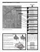
USERS DESCRIPTION OF FRONT PANEL 1 2 3 4 5 6 7 1. Output Terminals - For all functions as stated. 4 pins per block. 2. Two Logic Switches - These are no bounce logic switches. Give one signal state change per movement of switch. 3. Input Terminals for Logic Indicator LEDs - “A” input corresponds with “A” lamp, etc. 4. Logic Indictators - Eight LEDs. 5. Eight Data Switches - Lets output of 5V or 0V depending on position. 6. Output Terminal - For all functions as stated. 4 pins per block. 7.
INSTALL COMPONENTS TO PC BOARD Start Here R34 - 100kW 5% 1/4W Resistor (brown-black-yellow-gold) R35 - 100kW 5% 1/4W Resistor (brown-black-yellow-gold) R33 - 100kW 5% 1/4W Resistor (brown-black-yellow-gold) R32 - 100kW 5% 1/4W Resistor (brown-black-yellow-gold) R28 - 100kW 5% 1/4W Resistor (brown-black-yellow-gold) R27 - 100kW 5% 1/4W Resistor (brown-black-yellow-gold) R30 - 100kW 5% 1/4W Resistor (brown-black-yellow-gold) R31 - 100kW 5% 1/4W Resistor (brown-black-yellow-gold) R29 - 100kW 5% 1/4W R
INSTALL COMPONENTS TO PC BOARD Start Here R43 - 120W 5% 1/4W Resistor (brown-red-brown-gold) R42 - 120W 5% 1/4W Resistor (brown-red-brown-gold) S5 - 4-pin connector (see Figure A) R41 - 120W 5% 1/4W Resistor (brown-red-brown-gold) R40 - 120W 5% 1/4W Resistor (brown-red-brown-gold) R39 - 120W 5% 1/4W Resistor (brown-red-brown-gold) R38 - 120W 5% 1/4W Resistor (brown-red-brown-gold) S4 - 4-pin connector (see Figure A) R37 - 120W 5% 1/4W Resistor (brown-red-brown-gold) R36 - 120W 5% 1/4W Resistor (brow
INSTALL COMPONENTS TO PC BOARD Continue Start Here D25 - LED and Spacer (see Figure B) U9 - IC socket 14-pin U9 - 74HC04 IC (see Figure D) J27 - Jumper Wire (see Figure C) D24 - LED and Spacer (see Figure B) D23 - LED and Spacer (see Figure B) Continue D22 - LED and Spacer (see Figure B) U8 - 14-pin IC socket U8 - 74HC04 IC (see Figure D) D21 - LED and Spacer (see Figure B) D20 - LED and Spacer (see Figure B) J19 - Jumper Wire (see Figure C) D19 - LED and Spacer (see Figure B) R15 - 220W 5% 1
INSTALL COMPONENTS TO PC BOARD Start Here Continue SW4 - Slide switch SW5 - Slide switch SW6 - Slide switch SW7 - Slide switch SW8 - Slide switch SW9 - Slide switch (see Figure F) SW10 - Slide switch SW11 - Slide switch SW12 - Slide switch SW13 - Slide switch B7 - 4-pin Bredblox B8 - 4-pin Bredblox B9 - 4-pin Bredblox B10 - 4-pin Bredblox B11 - 4-pin Bredblox B12 - 4-pin Bredblox B13 - 4-pin Bredblox B14 - 4-pin Bredblox (see Figure E) B15 B16 B17 B18 Figure E Hold the bredblox down flush to the PC
RESISTANCE ANALYSIS OF DIGITAL SECTION Place the top panel onto the unit. Static testing of the digital section circuits. Do not plug the power supply into a 117 volt power source until all of the resistance readings check out. The values given below are approximate.
VOLTAGE ANALYSIS OF DIGITAL SECTION Plug the power supply into a 117 volt power source. The values given below are approximate.
TESTING THE DIGITAL SECTION TESTING THE LOGIC INDICATOR FUNCTION TESTING THE DATA SWITCHES TESTING THE LOGIC SWITCHES r Unplug the unit from the AC outlet. There are eight data switches to be checked. The output of the switches are 5V or ground depending on the position. Connect a wire to the SW1 test pin and the “A” test pin. The “A” LED should light when the switch is placed toward the top of the case. Repeat the same test on SW2, SW3, SW4, SW5, SW6, SW7 and SW8.
FINAL ASSEMBLY r Fasten the front panel in place with four #6 x 3/8” thread cutting screws, as shown in Figure I. r Fasten the PC board to the spacer on the front panel with a fiber washer and a 4-40 x 1/4” screw (from Power Supply Section) from the foil side of the PC board, in the location shown in Figure J. r Fasten the pots to the front panel with an 8mm washer and a 7mm nut, as shown in Figure I.
INSTALL COMPLETED UNIT INTO CASE r Place the strain relief onto the line cord as shown in Figure N. r Squeeze the two sections together with pliers as shown in Figure O. Then, insert the strain relief into the hole. r Lay the trainer inside of the case as shown in Figure P. r Align the holes in the bottom case with those in the trainer and secure it into place with four #6 x 1/2” AB screws and four #6 washer as shown in Figure Q.
CIRCUIT DESCRIPTION - DIGITAL SECTION THE DATA SWITCHES There are eight data switches labeled SW1 through SW8. The circuit is very simple. To perform the desired functions, there is a double throw double pole switch, wired as a single pole double throw. One end is connected to the 5V, the other to ground and the center lug is connected to the output. THE LOGIC SWITCHES The logic switches are also DPDT switches wired as SPST switches. The logic switches perform the same function as the data switches.
SCHEMATIC DIAGRAM -49-
QUIZ - DIGITAL SECTION INSTRUCTIONS: Complete the following examination, check your answers carefully. 1. The logic switches consist of . . . r A. two NAND gates and an SPST switch. r B. three OR gates. r C. two NAND gates and a DPDT switch. r D. one OR gate. 2. When the logic switch is thrown . . . r A. the contacts do not bounce. r B. a single transition is produced at the NAND gate output. r C. a multiple transition is produced at the NAND gate output. r D. none of the above. 3.
ELENCO® 150 Carpenter Avenue Wheeling, IL 60090 (847) 541-3800 Website: www.elenco.com e-mail: elenco@elenco.