DIGITAL / ANALOG TRAINER MODEL XK-550 A COMPLETE MINI-LAB FOR BUILDING, TESTING AND PROTOTYPING ANALOG AND DIGITAL CIRCUITS Tools and meter not included. Instruction Manual For Trainer with Organizer Case ELENCO Copyright © 2011, 1994 by ELENCO® All rights reserved. ® Revised 2011 REV-J No part of this book shall be reproduced by any means; electronic, photocopying, or otherwise without written permission from the publisher.
GENERAL SPECIFICATIONS FOR MODEL XK-550 Power Supplies: • 0V to 20VDC @ .5 amp (0V to 15V @ 1 amp) • 0V to –20VDC @ .5 amp (0V to –15V @ 1 amp) • +12V +5% @ 1 amp • –12V +5% @ 1 amp • +5V +5% @ 1 amp • 30V AC center-tapped at 15VAC @ 1 amp. • Load regulation all DC supplies less than .2V no load to .5A • Line regulation all DC supplies less than .2V 105 to 135V • Hum and ripple all DC supplies less than .01V rms • Short protection all DC supplies - Internal IC thermal cutoff • Fuse - 1.
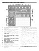
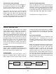
USERS DESCRIPTION OF FRONT PANEL CONTROL 7 8 9 10 11 12 6 13 14 15 16 17 18 19 5 4 20 3 2 1 1) Fuse holder - Easy access for replacement of 1.25A 250V fuse. 2) On-Off switch - Allows power to be applied to all outputs. Switch will light when on. 3) 4) 5) 11) Two logic switches - These are no bounce logic switches. Give one signal state change per movement of switch. 12) Selects five ranges of frequencies from 10 to 100,000 hertz.
INTRODUCTION package. They are, 5 independent power supplies, an analog trainer, a digital and a bredblock assembly trainer. We shall proceed in describing each trainer in the following sections. Congratulations on your purchase of the Elenco® Model XK-550 Digital / Analog Trainer. This trainer is designed to simplify designing of digital and analog circuits. It contains most of the necessary test equipment needed to build and test these circuits.
TESTING THE XK-550 DIGITAL ANALOG TRAINER The following paragraphs give detailed instructions on testing the digital / analog trainer. TESTING THE FUNCTION GENERATOR To test the function generator, you will need an oscilloscope. Connect the scope to the terminal marked FREQ., and the ground clip to the terminal marked GND. Adjust the waveform switch to sine, the coarse frequency switch to 1k and the amplitude control to maximum. Your scope should show a sine wave with an output of about 15Vpp.
TESTING THE LOGIC SWITCHES There are two logic switches and four conditions to be checked out. Connect a wire from the “X” test pin to the “A” logic indicator test pin. Connect another from the “X” test pin to the “B” test pin. TESTING THE DATA SWITCHES There are eight data switches to be checked. The output of the switches are at 5V or ground depending on position. Connect a wire to SW1 terminal and the “A” test pin, the “A” LED should light when the switch is placed toward the top case.
By the addition of a second diode and transformer winding we can fill in the gap between cycles as shown in Figure 4. This circuit is called full-wave rectification. Each diode conducts when the voltage is positive. By adding the two outputs, the voltage presented to capacitor C1 is more complete, thus easier to filter, as shown in Figure 2E. When used in 60 cycles AC input power, the output of a full wave rectifier will be 120 cycles. current.
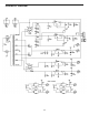
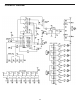
SCHEMATIC DIAGRAM -7-
SCHEMATIC DIAGRAM -7-
Transistor Q5 is called the pass transistor. It controls the current reaching the output. Transistor Q3 and Q4 are emitter followers. Their function is to raise the impedance of the pass transistor. Note that transistor Q2, Q3, Q4, Q5 and resistor R1 form a close loop. Also note that the feedback to the base of Q2 is negative, that is, when the base of Q2 goes positive, the output at emitter Q5 goes negative.
The XR-2206 is comprised of four functional blocks, a voltage controlled oscillator (VCO), an analog multiplier & sine shaper, a unity gain buffer amplifier and a set of current switches. The VCO produces a squarewave signal. This squarewave is sent to a shaper and converted into a sine wave. THE LOGIC INDICATORS There are eight logic indicators. Figure 9 shows the circuit. It consists of a 74HC04 IC. When the input is over 2.8V, the output of the IC will be low, drawing current through the LED indicator.
PARTS LIST Qty. Description Qty. Part# Resistors r 4 100Ω 1/4W 5% brn-blk-brn-gold r 10 120Ω 1/4W 5% brn-red-brn-gold r 1 200Ω 1/4W 5% red-blk-brn-gold r 1 220Ω 1/4W 5% red-red-brn-gold r 2 330Ω 1/4W 5% org-org-brn-gold r 5 1kΩ 1/4W 5% brn-blk-red-gold r 2 1.2kΩ 1W 5% brn-red-red-gold r 1 2kΩ 1/4W 5% red-blk-red-gold r 2 4.7kΩ 1/4W 5% yel-vio-red-gold r 1 6.8kΩ 1/4W 5% blu-gry-red-gold r 1 8.
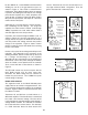
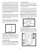
ORGANIZER CARRYING CASE The carrying case for the XK-550 Digital/Analog Trainer has been designed to hold a meter and many of the most important tools. The layout below shows a suggestive layout for equipment and tools. The sloped side pocket of the case next to the trainer can accommodate a wide range of different meters.
POPULAR METERS THAT CAN BE USED WITH THE XK-550 TRAINER Model M-2795 Model M-1700 Features Features • 3 ¾ digit, 4,000 count display • 3 ½ digit, 2,000 count display • Audible continuity test • Frequency to 15MHz • Data hold / rel.
WARRANTY POLICY Your XK-550 Digital / Analog Trainer has been tested and conforms to our rigid requirements on performance and durability. It is guaranteed to be free of defects in workmanship, materials and construction for a period of 2 years. If this product should fail during normal use within the first 3 months from the date of purchase, Elenco® will repair or replace the unit at no cost. For the remainder of the warranty period, a nominal service charge is required to cover shipping and handling.
ELENCO® 150 Carpenter Avenue Wheeling, IL 60090 (847) 541-3800 Website: www.elenco.com e-mail: elenco@elenco.